Note on joint motor feed forward command to hold a 3 link robotic arm up

February 15, 2023

Compensation for gravity induced error offsets using feedfoward inputs to arm joint motor PID controllers

If an arm joint has a torque induced by the weight of the arm or other loads under steady state conditions the motor must hold a constant counter torque . This torque requires a small constant current which in turn needs steady input command, delta. The motor controller usually contains a PID function which must hold the motor command . If we assume that Kd amd Ki are zero (for most controllers) then the command is held either by a feedforward input or and angle error equal to delta/Kp where Kp is the position feedback gain.
If the max command amplitude to the motor is scaled to 1 then we can compute
delta = -torque_gravity/(torque_stall*gr)
The minus means it is fed opposite to cancel the gravity torque.
gr is the motor gear ratio and torque_stall is the motor stall torque. Torque_gravity can be derived from the inverse kinematics for the center of masses on the links. For a three link arm the equations for each joint are :


3 link robotic arm


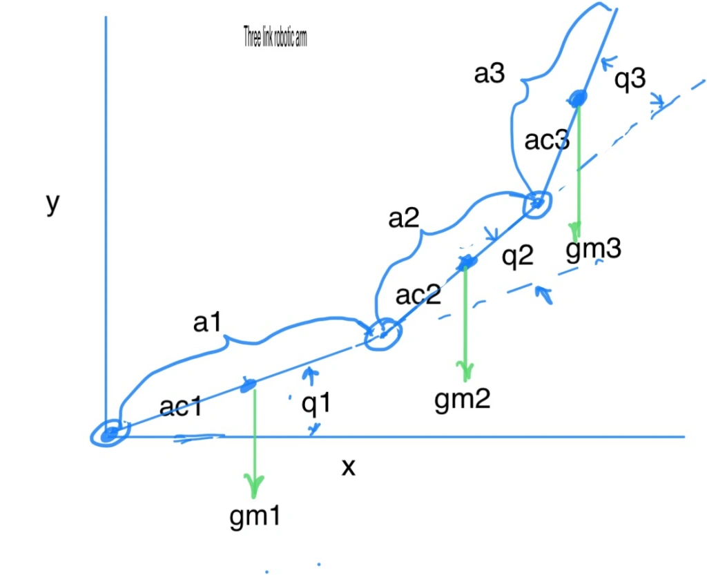
G(1)=g*(c1*(m1*ac1 + m2*a1 + m3*a1) + c12*(m2*ac2 + m3*a2) + c123*m3*ac3);
G(2)=g*((m2*ac2 + m3*a2)*c12 + m3*ac3*c123);
G(3)=g*m3*ac3*c123 ;

G(1),G(2) and G(3) are the downward gravitational induced torques at each joint.
q1,q2,q3 are joint angles
m1,m2,m3 are arm masses
a1,a2,a3 are link lengths
ac1,ac2,ac3 are link cg lengths from joint
g is acceleration due to gravity.

%sin and cos of angles
c1=cos(q1)
c2=cos(q2)
c3=cos(q3);
c12=cos(q1 + q2);
c23=cos(q2 + q3);
c123=cos(q1 + q2 + q3);

Since we have h torque_gravity and we then calculate the delta for each joint.. e.g. for joint 1

delta_1 = -G(1)/torque_stall_1*gr_1

If feed forward is used delta is fed directly to motor with a gain of 1.
If no feed forward then the motor command must be held by a q1 error = -delta_1/Kp


Steamworks 2017 FRC touchpad mockup using vex parts.   

February 9, 2017

Nice to have a lot of vex parts around to use in FRC field element or robot element mock ups.   This is a testing mockup of the touchpad which activates a light if any of the three posts holding the bottom plate are deflected at least 1/2 inch.    The vex green rubber links provide the flexibility for any aluminum beam to be pushed without jamming in the holes of the top plate.   


Vex Note: How a single flywheel ball shooter minimizes the effect of ball mass variations

May 28, 2015

Nothing but Net 2015/2016 competition game involves shooting 4 inch balls that can have a 10% variation in mass.    We know that trajectory range ,R = V^2/g*sin(2*theta) so it  is dependent upon the square of the ball release speed , V, and shooter elevation, theta.   Mass does not enter into the equation unless it affects V.

Ball release energy :

Suppose we use a Vex 5″ diameter wheel as a flywheel and rotate it a w_wheel angular speed.      As the ball leaves the shooter, it will have a V = r_wheel*w_wheel/2.  e.g. half of the flywheel tangential speed.    The ball will have a spin rate , w_ball = V/r_ball.    The energy of the ball, E_b , is the sum of the ball translational energy and rotational energy.

E_b = 1/2*m_ball*V^2 + 1/2*I_ball*w_ball^2

where I_ball = 2/5*m_ball*r_ball^2 (solid sphere of uniform density).

so Eb =  1/2*m_ball*V^2( 1+2/5)  .   (corrected 5/29 Was 1/2*m_ball*V^2( 1+4/5)  So the rotational energy adds  40% more to the translational energy.  Rewriting in terms of w_ball gives

E_b = .7*m_ball*w_ball^2*r_ball^2  

Wheel Energy:

E_wheel = .5*I_wheel*w_wheel^2.  where

I_wheel = m_wheel*(r_wheel*.84)^2  (ref blog post https://vamfun.wordpress.com/2015/05/17/finding-the-moment-of-inertia-of-a-vex-wheel-using-parallel-axis-theorem/)

Energy Conservation:

E_wheel_initial = E_wheel_final + E_ball     This assumes that the wheel is not being powered by the motor during launch and that the extra energy needed for the ball comes from the flywheel.   Also, friction and ball compression energy losses are assumed zero to simplify this analysis but can be significant in actual percentages derived.   I am focusing  on how increasing flywheel mass lowers the percentage range errors caused by ball mass variations.

E_wheel_initial/E_wheel_final = (1 + E_ball/E_wheel_final)

Lets expand E_ball/E_wheel_final

E_ball/E_wheel_final = (.7*m_ball*w_ball^2*r_ball^2)/(.5*I_wheel*w_wheel_final^2)

= 1.4*m_ball*w_ball^2*r_ball^2/(m_wheel*r_wheel^2*.84^2*(2*w_ball*r_ball/r_wheel)^2)

= .4954*m_ball/m_wheel

SInce  m_ball = 60 g and m_wheel = 180 g   m

_ball/m_wheel = 1/3

So  E_ball/E_wheel_final = .165    for a single 5″  wheel flywheel     .165/n for n flywheels.    So the ball energy is almost equal to the 1/6 final energy of the wheel

Range Tolerance analysis:

So how does R vary with m_ball from all this.   Well , we know the range is proportional to V^2 which is proportional to w_wheel_final^2 which is proportional to E_wheel_final.

From above E_wheel_final = E_wheel_initial/(1+ .4954*m_ball/m_wheel)

So due to proportionality of R and E_wheel_final we can say

R/R_0 = ((1+ .4954*m_ball_0/m_wheel)/(1+ .4954*m_ball/m_wheel))

where R_0 and m_ball_0 are the nominal values without errors.

We can use R range= R_0(1+ %e_r)   and m_ball = m_ball_0*(1 + %e_m_ball) to work with % changes.

Then with some manipulation we can get %e_r as a function of %e_m_ball

%e_r  = -%e_m_ball/(2.02*m_wheel/m_ball_0 +1 + %e_m_ball)

Now m_wheel = n*.180 kg   and m_ball= .06 kg  so we can write an approx.

%e_r = -%e_m_ball /( n*6.06 +1)     where n is the number of 5″ vex wheels.

Lets put in a few numbers:

Assume %e_m_ball = 10%  then the range error is

n = 1, %e_r =  -1.42%

n = 2, %e_r =  -.76%

n = 3, %e_r =  -.52%

n = 4, %e_r =  -.40%

n = 5, %e_r =  -.32%

So you see the benefits of having a higher  flywheel mass to ball mass ratio.   The use of  two 5″ wheels in a single wheel design can reduce a potential 10% range error from ball mass variations  to  1% ( less than a ball radius).   To keep the spin up time to a reasonable number of seconds requires about 2 393 motors per wheel so 2 wheels costs 4 motors.   So there is a motor tradeoff to get that  higher accuracy with heavier flywheels.


Vex Note: Motor power required to launch balls

April 23, 2015

The new vex game , Nothing but Net, could utilize a design similar to a two wheel tennis ball launcher.

Question: how many motors are required on the launcher?

The after a launch, the energy lost from the spinning wheels is transformed into ball kinetic energy and heat due to friction and ball compression.

After each shot the wheels are brought back to initial spin speed by the power of the motors.   The maximum time allowed for respinning is the cycle time of the firing sequence.    Lets take a look at the Vex game derived requirements:

Ball mass, m = 60 grams

Ball launch Speed, v =  6 m/s

Ball kinetic energy:K =  1/2*mass*v^2 = .5*.06*6^2 = 1.08 joules

Energy loss due to compression : E_c

Energy loss due to friction :  E_f

Time between shots: 1 sec

Average power required  p_avg = ( K + E_c + E_f)/ t

Force on ball during acceleration:

F =  d(m*v)/dt    or the change in momentum of the ball over the time of acceleration., dt.

dt can be approximated as the contact distance / tangential speed of the wheel , v.

The contact distance is about 3 cm so

dt= .03/6= .005 s

d(m*v) = .06*6 = .36 kg*m/s

hence F = .36/.005 =   72 newtons

Normal force on ball F_n = F/u_friction .    The normal (compression)  force on the ball is then

F_n = 72 newtons  assuming a u_friction = 1 which is possible with a sticky wheel.

The assumed  compression distance is about 1 in or 2.54 cm.  (To be verified later)

Hence Ec = F_n*d/2 = 72*.0254/2 = .91 joules. 

With good design, the friction loss in the drive train can be small (maybe .1 joules) so lets assume that E_c + E_f  are about equal to the K= 1.06 j so

p_avg = 2*K/t = 1.06*2= 2.12 watts   or 1.06 watts per motor.

We know the vex 393 motors have a max power = max_speed*max_torque/4 or about 4.5 watts  but they will overheat if run continuously at this power.   The PTC fuses will stop the motors if they run continuously with currents equivalent to more than  25% maximum torque (speeds less than 75% max speed).    At this operating point, the motors only deliver  3/4 max power or 3.4 watts.

There are also friction losses from the teeth of the spur gears.   I usually assume about 5% per 5:1 ratio.    A shooter wheel with a 25:1 gearing would lose 10% torque or energy at a given speed.

So the net power to the shooter wheel will be  .9*3.4 =  3.0 watts which is more than the 1 watt that we require.         

Extra friction?    

If the gear train has pressure on the axles from bearing blocks and possibly the collars are too tight so the wheels slow down quickly when coasting with motors disconnected, then over heating can easily occur.   e.g.  if friction uses up just 15% of the available torque, the motors will have to provide about 1 watt extra. which cuts our margin considerably.

Faster shot rate?

We assumed 1 shot per second…what happens with 2 shots per second….   Well, the power requirements almost double since we are using twice as much energy per unit time.    We would likely have to add extra motors.


60 in double reverse 4 bar linear linkage example

June 8, 2014

Here are some pictures of how a double reverse 4 bar using Vex 35 hole link arms. The main challenge is constructing a stable geometry. The lift has a middle link gear train to move the upper 4 bar in sync with the lower 4 bar.

Torque

Approx torque (inlb) required = 2*l_arm*(W_payload_lbs + W_lift_lbs + W_manipulator_lbs)*cos(angle)

height_delta = 2*l_arm*( sin(angle_finish) –  sin(angle_start))

where l_arm is the distance between pivots of the arms in inches, W_payload_lbs is game piece weight, W_lift_lbs  is the weight of the 3 arms used in the lift , W_manipulator_lbs  is the weight of the gripper attached to the upper arm and angle is defined relative to the horizontal.  The max torque occurs when the arms are horizontal or angle • 0 .

If you want to lift 4 1 lb Skyrise cubes with a 3lb lift weight , a 1 lb  gripper and a l_arm of 16 in you would need about 256 in lbs of torque.

As a rule of thumb I use 6 inlb of torque per motor for sizing  the number of motors.  This assumes 2  inlbs of elastic support , 1 inlb of friction and 3 inlbs from active current (about .9 amps) hold per motor used.   With these assumptions a 10:1 gearing and 4 393 motors might do the job.    The lift would take about 5 seconds to go full travel.  I’ll show a more exact torque derivation later.

Height change

With an  angle_finish = 75 deg and the angle_start= -60 deg  a 16 in arm reaches 59 in.  A 16.5 in arm reaches 61 in.   With a chain bar you could  clear an in or two more.20140608-214047.jpgSo 20140608-214101.jpg 20140608-214114.jpg


Homemade sea water for testing an ROV

March 16, 2014

Our GHCHS Algilata OpenROV project is not located near the ocean.   The OpenROV community has found that salt water operation can be flakey compared to fresh water due to low resistance between the salt water and  external wires that connect the battery tubes and the motors.     This post deals with making simulated sea water for testing the OpenROV in the lab.

Sea water conducts electricity due to the dissolved salts that produce ions for transporting charge between conductors submerged into the water.   Typical sea water has 35 parts per thousand  by weight of salt in water.    Since water at standard conditions weighs 1000 grams/liter then we can say that sea water has 35g of salt per liter.

I wanted to use just a cup measure to make a batch of sea water.     So I weighed one cup some Himalayan salt and found that it weighed 8 oz.  So we can estimate the weight of salt using this ratio…about 1  avoirdupois oz weight per 1  fluid oz .   Of course this will vary with the granularity of the salt due to variations in packing density but it should be good enough for conductivity testing.

Given that there are 28.3 grams per avoirdupois oz and  33.8 fluid oz per liter the sea water concentration of 35 gm per liter converts to  1.24 avoirdupois oz per 33.8 fluid oz or

1 avoirdupois oz per 27.2 fluid oz.

Since 1 cup (8 fl oz) of Himalayan salt weighed 8 avoirdupois oz then I would need to mix this with 217.6 fluid oz of water or 27.2 cups of water (1.7 gallons)

So I now have a simple rule of thumb for adding granulated salt to water using a volume measure:

volume ratio salt:water  1 : 27.2 

Other useful equivalents:   5.7 oz salt per gallon of water

                                              1/4 cup salt to 6 3/4  cup water

                                             1 tablespoon  salt to  1.7 cups water

Measuring salinity using conductivity:

Scientist often use conductivity to estimate salinity.   Standard units of conductivity are Siemans/meter  (S/m).    The electrical conductivity of 35 ppt salt water at a temperature of 15 °C is 42.9 mS/cm  (ref).   Thus 35 ppt equates to 42.9 mS/cm.

File:Conductimetrie-schema.png

Taken from wikipedia

Conductivity measurements assume that there are two parallel electrical plates of area A in water at a distance L apart.   If a voltage (V) is put across the plates and the current flow (I) measured then the conductivity  k = I/V*L/A =  L/(R*A)  where R is the resistance V/I.    Under ideal conditions the conductivity between the ROV wires and the water should be very low (high resistivity) but if a small area of copper is exposed  then conduction can occur. eg  some OpenROV forum members are finding resistance on the order of kiloohms rather than megohms.

Practically, if you put two probes from an ohm meter into water, the measured resistance will depend upon the area of the probe submerged and the distance between them.   You can use this as a reference to test your simulated sea water at home.

conductivity plug testerI made a simple  crude conductivity  instrument out of a two prong to three prong electrical plug adapter.   The plug prongs are separated by 1 cm and the exposed area between the prongs is almost exactly 1 sq sm.  I covered the non-facing sides with tape or you  could use paint or nail polish to insulate the surfaces from water.   See photo.

In the field,  dip the plug tester prongs into the water and measure the resistance between them.  Note the temperature since conductivity varies a lot with temperature.

Theoretical  plug conductivity prediction for sea water.

k = L/(R*A)  = 1/R            S/cm

= 1000/R    mS/cm

Typically sea water resistance in ohms for this homemade instrument  at 15 deg C would be

R_ohms = L/(A*k)= 1cm/(1cm ^2)/(42.9 mS/cm) = 1000/42.9 = 23.3 ohms

When creating your simulated sea water at  home you would like to have similar conditions.   You would add salt to your water tank/tub until the resistance level matched.

Testing:

I did a quick conductivity test by dissolving 1 tablespoon of Himalayan sea salt in 1 3/4 cups of water.   The measured resistance  using my plug conductivity tester was around 3 kohms with a VOM meter and using the voltage / current method the resistance was 230 ohms.     So it is reading much higher than the theory.    The test was done at 70F (21C).   Temperature changes the conductivity about 2% per degree.  The measurement was 6 deg C higher so at most we would expect a 12%  increase over the 15 C reference.

The absolute measurements can vary too much with conductivity so I would recommend just using the 35g/kg  salt/water mixing method or just doing relative conductivity measurements..i.e.  matching field conductivity to home conductivity under similar conditions.


Making Fat Shark FPV goggles work with OPENROV ($7 solution ?)

March 7, 2014

Robodox ROV team is building an OPENROV 2.5 kit for Algalita Research Foundation to take on their July 2014 Pacific Gyre expedition.    The ORV catamaran , named Alguita, will take a team of scientist to sample and analyze the effects of plastic in the ocean on marine species.    To help extend their capability to locate plastic concentrations they are utilizing a variety of sensors.   One is a Phantom quadcopter drone equipped with a Fat Shark Predator V2 FPV system.

IMG_7776The Predator V2 uses two LCD screens to display video in goggles show below.

IMG_7783

The Predator specifications are shown here.   Pictures are sent from an aerial camera platform to the goggles in real time over a 5GHz wireless link.

openrov 2.4The underwater ROV that Robodox is building will do a similar function by transmitting HD camera video to a topside Laptop computer over a two wire tether.    It would be desirable if the Fat Shark video goggles could also display the Laptop video sent by the ROV.    Unfortunately the video formats are not compatible without a VGA to composite video converter.   I did a little research into how this could be accomplished.

Here is the plan:

1) purchase a Tmart $3  VGA to A/V RCA converter.  03m-VGA-to-SVIDEO-and-RCA-Female-Cable_320x320

2) Purchase an $3.50 Allelectronics 3.5mm  A/V  to RCA cable with 6 ft  extension to allow freedom of movement between the laptop and the goggles.

3) Plug the VGA converter into the laptop VGA output port and then plug the 3.5mm A/V cable into the Fat Shark video input port via the extension.   Turn off the Fat Shark wireless receiver.

Seems like this would work…yet to be tested.

Wireless Connection to the Fat Shark

The transmitter side of the Fat Shark FPV system involves a small 600 TVL camera that plugs into a transmitter compatible with the receiver in the goggles.

Fat Shark tranmitter

If the transmitter is available on the boat (ie a spare that is used for the Phantom drone) then the output of the converter could be used in place of the camera output that plugs into the transmitter.   This way the goggles could be free from any wires. There would be another plug adapter to mate the composite video RCA plug to the plug on the xmitter.


Robodox performs well at 1st Week FRC Inland Empire Regional

March 5, 2014

Robodox performs well at 1st Week FRC Inland Empire Regional

GHCHS Team 599 Robodox attended the 2014 Inland Empire Regional FRC competition. We collected the Engineering Design award and also the competition finalist award and medals. It was a well run competition and we had a great time. Once again we had a top performing robot that got beat by a stronger no 1 alliance. We made an operational mistake  in the finals that cost us the first match by breaking communication during setup and causing our Crio to need resetting after the match started and we sat out the Autonomous plus some seconds.    Our alliance partners 294 and 4139 were having functional problems in the second so we were soundly trounced by the winning alliance led by 1678 citrus circuits who teamed up 399 and 4161.   The 2nd final match (see video) was a thing of beauty with 1678 and 399 performing two truss catches and racking up a 229 to 72 score.  Hopefully we can redeem ourselves at  our next regional  in Sacramento where we will once again tangle with 1678 citrus circuits from Davis.   Also, thanks again to 294 for selecting us for the direct eliminations.

Winning the engineering design award means a lot to us since this year we focused on doing a 3D Solidworks design supported by solid prototyping. All fabrication was done based upon automated drawings made from the 3D model. This the best looking robot we have done in years and clearly the most durable. See this post for picture.
Lots more pictures on my facebook page.
The choo-choo catapult reset mechanism performed well so long as we kept the linkages in good order. The high forces caused holes in the linkages to elongate after a day worth of shooting. This was anticipated so we brought three spares and used them all. We will use steel linkages rather than aluminum at our next competition so they should last longer.

Robodox also ran the robot First Aid Station and the spare parts booth. We also had on display our underwater ROV which will be used by Algalita Research Foundation to do plastic pollution exploration in the Pacific Gyre this summer.


2014 Frc Aerial Assist Robodox 599 Robot ready to compete

February 26, 2014

 2014 robot pre bag

Come see us compete this Saturday and Sunday with our new robot at 2014 Frc Arial Assist Inland Empire Regional,   We will also have our Algalita underwater ROV on display to play with.

Robot is a catapult with Choo Choo reset mechanism.  < 2 sec recock.   Full range capability allows multi ball shooting capability during 10 second autonomous.   Drive is a dual speed 4 CIM West Coast configuration.  Pneumatic intake arm control.

Preview video of the Anesthesiologist.


Algalita OPENROV ready for testing

February 25, 2014


I wanted to share what the Robodox Algalita ROV engineering team has been up to for the last two months.  See Robodox Engineering ROV for ORV blog post : Feburary Status Update .   I am happy with their progress and we expect to have the underwater robot ready for the Algalita summer voyage.

Relevant posts:

Dec 20 2013 OpenROV Berkeley Trip

Robodox 599 Algalita 2014 Youth Summit Video Submission

Use of Robotics to support Algalita research into the Pacific garbage patch

Links:

http://robodoxrov.wordpress.com (build blog)

Algalita ROV project facebook page