Note on joint motor feed forward command to hold a 3 link robotic arm up

February 15, 2023

Compensation for gravity induced error offsets using feedfoward inputs to arm joint motor PID controllers

If an arm joint has a torque induced by the weight of the arm or other loads under steady state conditions the motor must hold a constant counter torque . This torque requires a small constant current which in turn needs steady input command, delta. The motor controller usually contains a PID function which must hold the motor command . If we assume that Kd amd Ki are zero (for most controllers) then the command is held either by a feedforward input or and angle error equal to delta/Kp where Kp is the position feedback gain.
If the max command amplitude to the motor is scaled to 1 then we can compute
delta = -torque_gravity/(torque_stall*gr)
The minus means it is fed opposite to cancel the gravity torque.
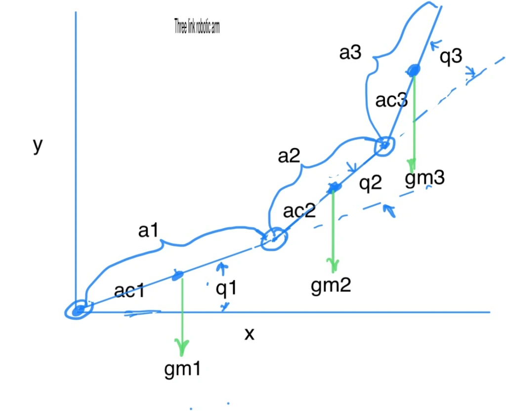
gr is the motor gear ratio and torque_stall is the motor stall torque. Torque_gravity can be derived from the inverse kinematics for the center of masses on the links. For a three link arm the equations for each joint are :


3 link robotic arm


G(1)=g*(c1*(m1*ac1 + m2*a1 + m3*a1) + c12*(m2*ac2 + m3*a2) + c123*m3*ac3);
G(2)=g*((m2*ac2 + m3*a2)*c12 + m3*ac3*c123);
G(3)=g*m3*ac3*c123 ;

G(1),G(2) and G(3) are the downward gravitational induced torques at each joint.
q1,q2,q3 are joint angles
m1,m2,m3 are arm masses
a1,a2,a3 are link lengths
ac1,ac2,ac3 are link cg lengths from joint
g is acceleration due to gravity.

%sin and cos of angles
c1=cos(q1)
c2=cos(q2)
c3=cos(q3);
c12=cos(q1 + q2);
c23=cos(q2 + q3);
c123=cos(q1 + q2 + q3);

Since we have h torque_gravity and we then calculate the delta for each joint.. e.g. for joint 1

delta_1 = -G(1)/torque_stall_1*gr_1

If feed forward is used delta is fed directly to motor with a gain of 1.
If no feed forward then the motor command must be held by a q1 error = -delta_1/Kp


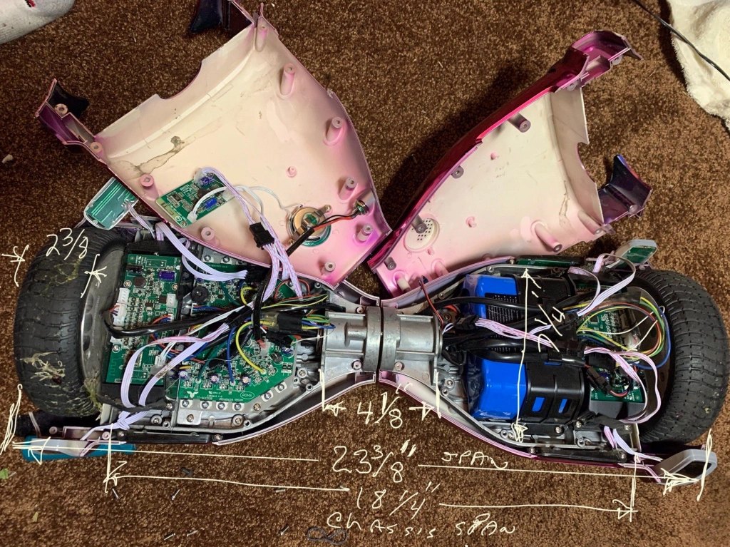
Flying Fire Hose blog #1. Hover-1 H1 Hoverboard tear down

December 23, 2020

New project underway….to robotically fly a fire hose with dual water jets attached using a hoverboard hack.

Hover-1 H1 specs. https://hover-1.com/hover1-h1-specs

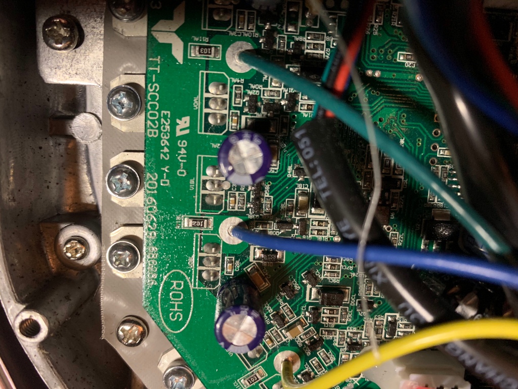
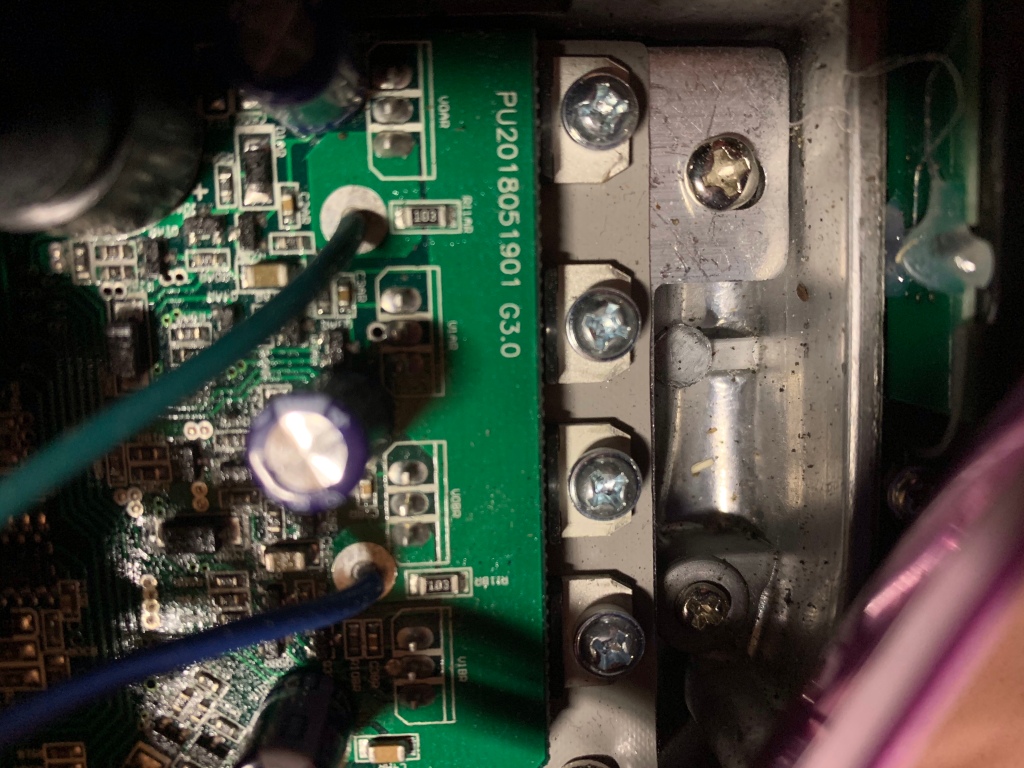
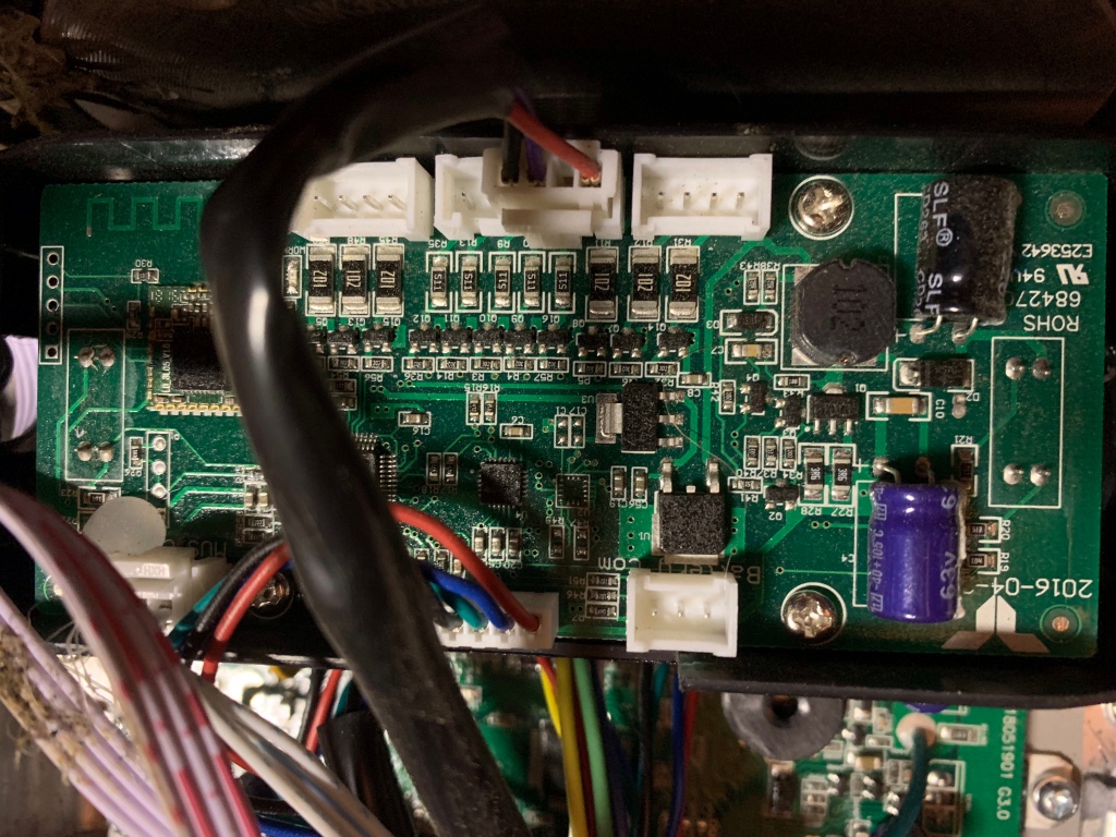
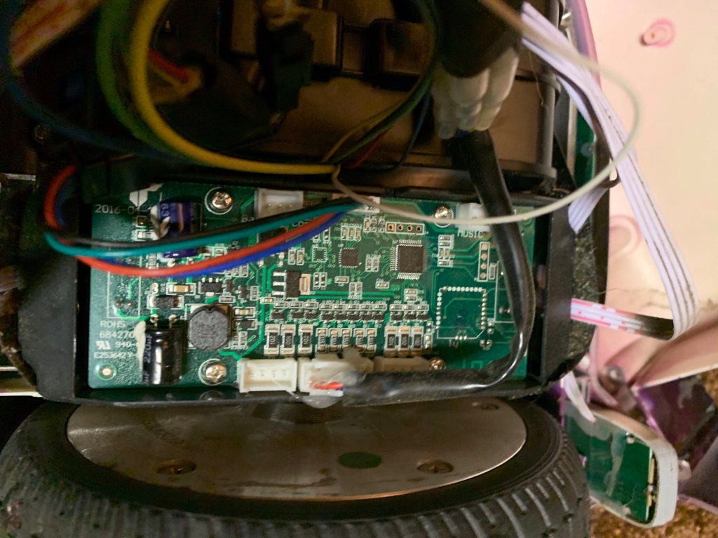
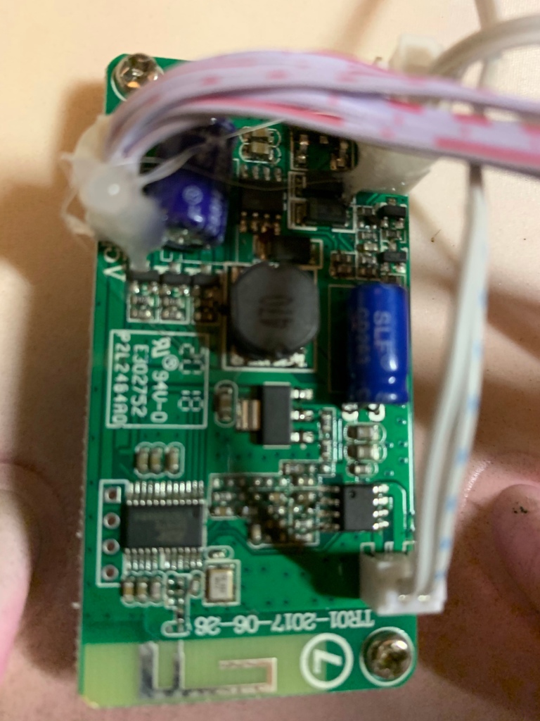
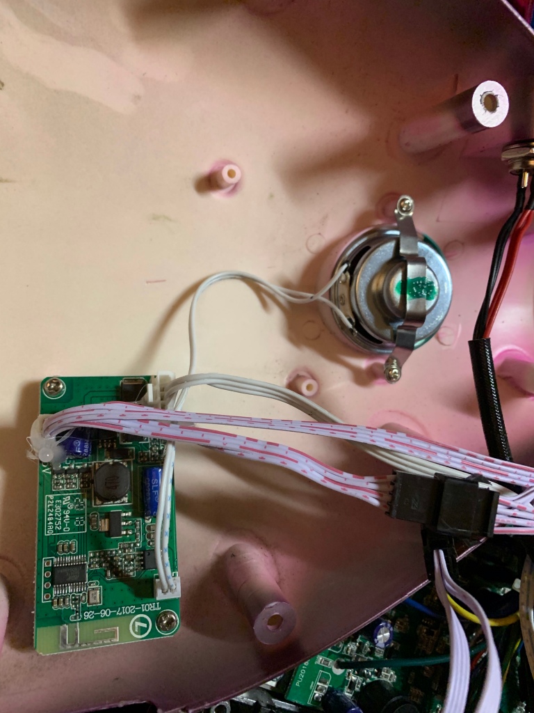
Here is a look inside with a few dimensions. Bought used..smell of burnt electronics but handles nicely. Around the house uses about 1% to 2 % of battery per minute according to Bluetooth app.


Getting my feet wet with Arduino Uno

July 18, 2013

Arduino Uno

I have tried to stay away from Arduino mainly because I didn’t want to learn a whole new culture. However, my AlgalitaROV project uses the OPENROV electronic architecture which employs a Cape that uses the Arduino Uno processor which in turn attaches to a BeagleBone Black(rats…another processor culture to learn).
Downloaded and installed the Arduino SDK 1.0.5 from arduino.cc and read through the getting started and reviewed the types of commands it uses. I bought a Arduino Uno starter kit from amazon ($32) which has a breadboard and some jumper wires. plugged in the Arduino Uno and it installed automatically without updating the drivers as suggested in the instructions. First observations:

1) the general purpose I/O (GPIO) are 5 volt at the breakouts. This is great since it is compatible with Vex parts. Current is o limited to 40ma per pin.

2) it can be powered from the USB cable or an external supply that must range from 6v to 20v with a recommendation of 7v to 12v.

3) Software wise in the Arduino you write a void setup() function and a void loop() function. These functions are called automatically by the operating system. setup() runs once and the loop() runs continuously…meaning the hidden main() function contains a while(true){loop()} structure that runs after the setup() runs. By contrast the Vex RobotC template calls a function pre_autonomous() once and executes separate tasks autonomous() and usercontrol(). usercontrol contains an explicit while(true){} which the programmer can change. Not sure that Arduino gives us that capability.

3)There are plenty of software examples and the language is close to C. The only function that seemed misnamed was analogWrite(pin,duty). This doesn’t write an analog output to a d/a hardware as one might assume but puts a 5 volt PWM signal output on a PWM capable GPIO pins. On the Uno 6 of the 14 GPIO pins are PWM capable (3,5,6,9,10,11). Not sure why they didn’t just call it PWMWrite().

4)Servo library is available for use but be careful with servo.write(int val).

Here is the function code from the servo library.  Note that if val is >544 then the command is assumed to be in microseconds rather than servo degrees.  Also note if it is less than 544 that the degree values are truncated to valid servo range of [0,180].    So a val = 255 will produce a 180 degree command.

void Servo::write(int value)
{
  if(value < MIN_PULSE_WIDTH)
  {  // treat values less than 544 as angles in degrees (valid values in microseconds are handled as microseconds)
    if(value < 0) value = 0;
    if(value > 180) value = 180;
    value = map(value, 0, 180, SERVO_MIN(),  SERVO_MAX());
  }
  this->writeMicroseconds(value);
}

First Script.
We need an r/c brushless motor driver. The ESC needs a standard servo drive signal. So I hooked up a Vex pot to the board and read its value [0, 1023] and scaled it to [0,180] which is given to a canned servo program object which has a servo.write which generates the proper servo output to a specified pin.  A motor is a continuous rotation servo  so 0 value represents max reverse speed and 180 value gives max forward speed.   I also included a serial printout of the value to the laptop console.
Hardware Setup:
[click on picture to expand to full size]

Shows breadboard wiring , motor 7.2v battery and external board 5 volt power supply

Shows breadboard wiring , motor 7.2v battery and external board 5 volt power supply

It is important to note that the motor is powered by a separate battery since it draws more current than the board can supply.

Closeup of arduino wiring

Closeup of arduino wiring

Full test setup

Full test setup

Mymotorcontrol.ino

// Controlling a servo/motor position using a potentiometer (variable resistor) 
// by Chris Siegert:  vamfun@yahoo.com   https://vamfun.wordpress.com
// adapted from  Michal Rinott servo code  
// connect the center pin of a potentiometer (pot) to the potpin.  Connect the other two pins to the arduino 5v and ground pins.
// connect the white wire of the motor pwm cable to the servopin.  
// Important!! Connect the red and black wires to an external motor power source. 
// The arduino is not designed to deliver enough current to drive a servo/motor.
#include <Servo.h> 

Servo myservo;  // create servo object to control a servo or motor. 
int servopin = 9; //connects servo to pin 9 which is a pwm pin.
int potpin = 0;  // analog pin A0 used to connect the potentiometer
int val;    // variable to read the value from the analog pin 
int cmd = 0; // cmd to motor [0 to 180]
int cnt = 0; // program cycle counter 
int cnt_max = 33;   // this is the number of delay cycles between serial printouts. (15ms per cnt) 33 counts gives about 2 per second)  
void setup() 
{ 
  Serial.begin(9600);   //start up the serial data port at 9600 baud 
  myservo.attach(servopin);  // attaches the servo on servopin number to the servo object void loop() 
{ 
  val = analogRead(potpin);            // reads the value of the potentiometer (value between 0 and 1023) 
  cmd = map(val, 0, 1023, 0, 180);     // scale it in degrees of servo rotation(value between 0 and 180) 

  myservo.write(cmd);                  // sets the servo position according to the scaled value in deg 
  cnt++; 
  if(cnt > cnt_max)                  // this sets time between serial print outs to cnt_max cycles  or about (15 ms*cnt_max)
  {
    Serial.println(cmd);  
    cnt = 0;      // debug value
  }
  delay(15);                           // waits for the servo to get there 
}

Proposed method of incorporating PTC resistance into my Vex motor models

November 24, 2012

rev 11/25/2012

The motor model uses two resistances: motor resistance Rm and  series resistance Rs.   These are used to compute time constants and current contstants for generating waveforms for the Hbridge ON phase and OFF phases.

tau_ON = L/(Rm + Rs)

tau_OFF = L/(Rm)

Also the steady state current constants are affected by resistances:

i_ss_ON = (V_battery – V_bemf)/(Rm +Rs)

i_ss_OFF = -(V_diode + Vbemf)/Rm

These constants basically assume that the PTC resistances are incorporated into Rs during the ON phase and negligible for the OFF phase.   Typically, Rs that best fits test data is .3 ohms according to Jpearman.   The Rm  is 1.5 ohms for a 393 and 2.5 for a 269 motor.

Incorporating the PTC requires an understanding of the Vex power distribution schematic shown below:(Click to expand)

The two PTC resistances involved are the Cortex Rptc_c and the motor PTC resistance Rptcm.  They affect the controller voltage and the time constants of the H-bridge.

Voltage Drop: Rptc_c causes a voltage drop between V_battery measuring point and the controller.  The voltage drop is Rptc_c*i_1_5 where i_1_5 is the sum of the current draws from ports 1-5 on the cortex.  These currents have been assumed to be the average currents from each of the motors in the PTC monitor software.   This however is very conservative since the current draw from the battery is zero for a motor during the OFF phase of the PWM controller cycle.      For example, when the motor current of a 393 is at its safe current of .9 amps, the ON phase current is about 0.33 amps or 37% of i_m.

The current model  computes the average current per PWM cycle as

i_avg = i_ss_ON*duty_ON + i_ss_OFF*duty_OFF

where  i_ss_ON*duty_ON  is the average current over a PWM cycle caused by the ON PWM pulse.  This should be used in the computation of the cortex currents rather than the total motor current i_avg.

Also,

Vc = V_battery – Rptc_c*i_1_5

should be used as the input voltage to the current model rather than V_battery which we are using now.

Rptc_c for the HR16-400 is only 18 mohms.  Typically the maximum current for a cortex bank is from 3 motors at stall or 4.8*3 = 14.4 amps.   This can lead to a voltage drop of  .26 volts.       One might argue that Rptc_c effects can be ignored.

Time Constants: By inspection from the figure we can see that the series resistances in the controller-motor loop in series with the motor resistance Rm are slightly different for the ON and OFF phases.

R_s_ON = Rptcm + 2*Rwire +  2*Rfet.

R_s_OFF = Rptcm + 2*Rwire + Rfet.   (it has one less FET in its path)

The time constants are :

tau_OFF = L/(Rm + R_s_OFF)

tau_ON = L/(Rm + R_s_ON)

where :

Rwire is the wire resistance down stream of the controller.  The upstream wire resistance is assumed negligible.    1 foot of wire is assumed for each power and ground leg and at 10 mohms per ft, Rwire = 10 mohms.

Rfet is the ON source-drain resistance of the MOSFET.  This is about 20 mohms for both the high and low side MOSFETs.

Rptcm is the motor PTC reference resistance at 25 deg C.   For the 393 Rptcm = 140 mohms and for the 269 Rptcm = 110 mohms.

Plugging in to the above formulas for a 393 motor gives

R_s_OFF = 140 + 20 + 40 = 200 mohms (.2 ohms)

R_s_ON =  140 + 20 + 20 = 180 mohms (.18 ohms)

Since there is only 20 mohms difference and these are added to Rm which is 1500 mohms I would recommend using one time constant:

tau = tau_ON = tau_OFF = L/(Rm + R_s)   where R_s = 200 mohms.

Using a similar argument for the 269 we would have R_s = 170 mohms

Current constants:

The current constants are modified similar to the time constants:

i_ss_ON = (V_c – V_bemf)/(Rm +Rs_on)  …. using V_c rather than V_battery

i_ss_OFF = -(V_diode + Vbemf)/(Rm + Rs_off)

We can also use the approximation Rs_on = Rs_off = Rs  as we did for the time constants.


Having said all this , the differences discussed may or may not be noticible in the results and I wouldn’t be too uncomfortable keeping things the way they are since much of the testing done by Jpearman has shown adequate results with the present model.
Relevant links:

https://vamfun.wordpress.com/2012/08/31/smart_ptc_monitor-beta-code-release/

https://vamfun.wordpress.com/2012/08/18/smart-software-monitor-keeps-ptc-fuses-from-tripping/

https://vamfun.wordpress.com/2012/07/21/debridge-controller-current-vex-jaguarvictor-draft/rivation-of-formulas-to-estimate-h-


smart_PTC_monitor beta code release

August 31, 2012

Ok, I’ve got the RobotC code used in my smart_PTC_monitor developed to a point where I would let others play with it.   I originally used a single timed iterative loop that ran in the same task as  autonomous and user modes.  I decided to create a separate task that simplifies the user interface so normal programming can occur without any of my constraints.  When done, the user functions are easily inserted into my template to seamlessly add the PTC monitor protection capability.    The program is self documented with liberal commenting but I am sure people will have a lot of questions.   I am putting it out without fully testing all the functions to get early user feedback and if it proves to have utility, I will put out a more mature version that includes user feedback.

Please post your comments to the Vex forum thread where the program is introduced.   Thanks


Download:  https://dl.dropbox.com/u/17455717/smart_PTC_monitor_template.beta.8.27.12.c


Below is a copy of the introduction comments in the program:

//*************************************************************************************************************** // smart_PTC_monitor_template.beta.8.27.2012.c   Rev 0

// This program is an open source beta version of a competition template for Sack Attack.  It adds a task // called smart_PTC_monitor which uses current and PTC temperature models to manage a current_limiter function // which can keep hardware PTC fuses in the motors,cortex and power expander from ever tripping.

// Program Author: Chris Siegert aka Vamfun on the Vex forums. // see my blog: vamfun.wordpress.com  for model details and vex forum threads on subject // email: vamfun@yahoo.com // Mentor for team 599 Robodox and team 1508 Lancer Bots

// Teams are authorized to freely use this program , however, it is requested that improvements or additions be // shared with the Vex community via the vex forum.  Please acknowledge my work when appropriate.  Thanks

// Scope and limitations: // Program assumes that servo currents are zero.  If servo position is known, then currents can be modeled. // Testing has been limited to 393 motors and 3wire motors, however, the program handles  269 motors. // Periodic updates to the models will be made and posted on the Vex forum as more testing is done. // Program handles the Power Expander PTC when the ports are entered with provided #defines // All other motor ports are automatically configured to calculate the correct currents for each PTC

// Basic Instructions: // Write your program as you normally would.  When done, put your autonomous code in place of my_autonomous() // and your user code in place of my_user().  Then do a find and replace to change all the “motor” functions to // “motor_input” i.e.  motor[Left_motor] –> motor_input[Left_motor].

// Put all your encoder speed calculations into  void compute_speeds() function and assign speeds to M[port].speed variable. // You can read these speeds from the global array whenever you need them.  This loop runs at about 100ms update rate.

// Use a #define or switch to create a // PTC_monitor_engage boolean and set true to engage the monitor.

// Tell the program which ports are used by the Power Expander as shown in the example below: // #define PE_CH1  UNUSED // if used put port number …. i.e. PE_CH1  port1  else put the #define UNUSED

// #define PE_CH2  Right_drive_motor  //use setup names

// #define PE_CH3  port3  //use port name

// #define PE_CH4  1  // use integer = to port number -1.  This is motor port2

// Initialize the PTC temperatures using these #defines: // #define T_0_DEG_F  (72.) //Set robot ambient temperature here.  If you are in a hot gym…this might be 85 deg

// #define T_M  (100.) //100 deg C =Setpoint temperature for the PTC current monitor.

// Motor currents and PTC temperature data are held in a global state matrix M[] which is a structured array that contains // the motor PTC/current data in the first 10 elements (index 0 to 9) and the non motor PTC’s data in the next three elements. // M[10] , M[11] and M[12] pertain to the cortex1_5,cortex6_10 and power expander PTC states respectively.

// Program uses two update rates: The current_limiter updates at PTC_TASK_DELAY_MS which is 15ms // and the temperature calculations are set to run at about 6 times {PTC_TASK_DELAY_MS + subtasks delays) ~= 100ms. //****************************************************************************************************************


Derivation of formulas to estimate H bridge controller current (Vex, JAGUAR,Victor)

July 21, 2012

I Introduction:

In 2009 I spent a lot of time in a First Chief Delphi forum thread  with some motor experts figuring out why a JAGUAR controller was linear in speed with duty cycle and a Victor was non_linear.   An example of this phenomenon is shown here for a Vex 269 motor being driven by several types of controllers.   Data is from my Excel H_bridge model All controllers have basically the same design except for the PWM frequency.  The extremes are for the JAGUAR is 15k hz and the Victor 884 is 120 hz.

Turns out that the motor time constant tau = L/R (motor inductance/motor resistance)  relative to the PWM pulse period T is key to the phenomenon.  I call the ratio of these lamda = T/(L/R).

I developed some analytical models for this forum which can predict the waveforms and average currents with good accuracy for various types of controllers and I want to show the basic mathematical derivation in this post.   I have updated the equations to include the Vex controller which has a PWM frequency near 1250 hz which is in between the JAGUAR and the Victor 884.

It is assumed that the reader has a basic knowledge of how an H bridge works.  If not, there are many good references on the internet and I might suggest the following:

 Hbridge  Secrets

H bridge Wikipedia

The type of H bridge that I am assuming is often called a high side switcher  or  asynchronous sign magnitude H bridge.   Basically, for a given motor direction, two switches are used while the others remain open.

General note.. clicking on any figure will expand it to maximum size.

On the high side switcher, a lower switch  is closed and the upper switch  is driven by a PWM waveform and opens and closes with period T and duty cycle D.

When the PWM pulse is high, the ON current flows from the battery  through the motor as shown.

When the PWM pulse is low, the OFF phase current flows through the diode as shown.

II  H bridge Equivalent Circuit

The equivalent circuit for one motor direction of the H bridge is just a switch and a battery in series with system resistance R_s and a motor (This is modeled as an  inductor , resistor R , voltage source = V_bemf in series) as shown in the “Simplified DC motor switching model.”

There is also a diode that is across the motor to allow current to flow when the switch is opened. The switch opens and closes with a PWM drive with duty cycle D and  period T.

(click figure to expand)When the switch is closed current increases exponentially from its last value toward a steady state value of i_ss_on.   When the switch is opened, current decays through the diode toward i_ss_off.  If it reaches zero then current stops and remains at zero until the next on pulse.

.

We can write the differential equations for these two phases.   It is important to note that these equations are for the controller direction that puts a positive voltage across the motor.   When the motor is commanded in the opposite direction some sign changes must be made to the equations.   Where ever you see a V_b and a V_d  simply change the signs and the equations will be correct for the current.  The steady state speeds also require replacing i_free with -i_free.    These will be added in the software implementation by using the sign(command) which tests the sign of the command.   Duty is always positive and for Vex is defined as D =  abs(command/127) where the command ranges between -127 and + 127.

III ON phase Current

When the switch is closed, the voltage across the motor V_m = -V_d > 0 so the diode is reversed biased and i_d = 0 .  Using Ohms law  and the fact that i = i_L  ( no current is flowing through the diode in this phase) gives

0 = V_b – V_bemf – V_L   – i*(R +R_s).

But the voltage in the inductor V_L = L*di/dt    So we have a differential equation

di/dt = ( V_b – V_bemf – i*(R +R_s) )/L

In the steady state, di/dt–>0  so the steady state current

i_ss_on = (V_b – V_bemf)/(R +Rs)

Putting it in terms of motor time constant

di/dt = (i_ss_on – i)/tau_on   where tau_on = L/(R_s + R) .

The ON closed form solution of the differential equation can be shown to be

i_on =  i_0*exp(-t/tau_on)  + i_ss_0n *(1 – exp(-t/tau_on)) 

where  i_0 is the initial current.

At t = DT  the maximum occurs and using the substitution  lamda = T/tau_on  we can write

i_max = i_o*exp(-lamda*D) + i_ss_on*(1 – exp(-lamda*D))

IV OFF phase current

When the switch is opened current in the motor coil finds a path through the diode.

i_L = i_diode

0 = V_bemf + V_L + i_L*R  + V_d

Substituting for V_L = L*di_L/dt  gives the differential equation

di_L/dt =- (V_bemf + V_d  + i_L*R)/L        and

i_ss_off = -(V_d + Vbemf)/R             when di_L/dt –> o.

The OFF closed form solution is

i_off =  i_max* exp(- t’/tau_off) +  i_ss_off *(1 – exp(- t’/tau_off))

where again tau_off = L/R .    Here i_max is the maximum current of the ON phase which occurs at the exact point that the switch opens or at t = D*T so   i=max is the initial current for the OFF phase.    t’ is the time from the switch opening.   I. E.   t’ = t – D*T  for t> DT.

V Approximation for Vex motors

The  time constants  for the ON and OFF  phases are slightly different due to the addition of Rs during the switch ON phase.    I.e.  tau_on = L/(R+Rs)   and  tau_off = L/R.   For the Vex motors, Rs << R so the following equations will use the approximation  tau= L/R = tau_on =tau_ off.

VI Final Current Value,  i_final

During the OFF phase the current will decay to a final value of current.  The point  in time where it reaches it final value will be defined  t'(final) = D’T .   Substituting t’ = D’T  and lamda = T/tau  into i_off  equation gives

i_final  =  i_max*exp(- lamda*D’) + i_ss_off*(1 – exp(-lamda*D’)

VII Initial current i_0

A steady state solution requires that

i_0 = i_final

otherwise after a cycle is completed  the next initial condition will be different from the initial condition for the last cycle.

Using this equality and substituting i_max into the i_final equation gives

i_0 =( i_o*exp(-lamda*D) + i_ss_on*(1 – exp(-lamda*D))*exp(-lamda*D’) + i_ss_off*(1 – exp(-lamda*D’)

Solving for i_0 gives

i_0 = ( i_ss_on*(1 – exp(-lamda*D))*exp (-lamda*D’) + i_ss_off*(1 – exp(-lamda*D’))/(1 – exp(-lamda*D)*exp(-lamda*D’))

(Click to expand figures)

Recall as shown in this figure, the current can be continuous or discontinuous.

Case A: Continuous current

If the diode conducts during the whole OFF phase then steady state current requires i_0 = i_final and

D’ = 1-D .  That is i_final occurs exactly at the end of the period.  Substituting for D’ and i_final in the i_o equation gives

i_0 = ( i_ss_on*(1 – exp(-lamda*D))*exp (-lamda*(1-D))+ i_ss_off*(1 – exp(-lamda*1-D)))/(1 – exp(-lamda*D)*exp(-lamda*(1-D)))

Case B: Discontinuous current

In Case B, the current tries to reverse sign during the OFF phase but is clamped to zero by the diode for the remainder of the PWM period.   So both the final and initial currents are zero in the steady state.

i_final = i_0  = 0

With this constraint, we can solve the i_0 equation for D’ at the point where the waveform reaches 0.

0 =  i_ss_on*(1 – exp(-lamda*D))*exp (-lamda*D’) + i_ss_off*(1 – exp(-lamda*D’)

exp(-lamda*D’) =  -i_ss_off/(i_ss_0n*((1-exp(-lamda*D) – i_ss_off))

and taking the ln of both sides

D’ =  – ln( -i_ss_off/(i_ss_on*((1 – exp(-lamda*D) – i_ss_off)* lamda)

Or in terms of i_max,

 D’    =  – ln( -i_ss_off/(i_max – i_ss_off)* lamda)

VIII  AVERAGE CURRENT PER CYCLE  – i_avg

Our primary interest in developing current equations is to determine an expression that can be used to control the long-term behavior of a motor relative to a slow PTC fuse or setting a the steady state speed for a robot.    What we want is the equivalent DC current over a cycle  which is the average current per cycle.   This is computed by integrating the area under the current response and dividing by a cycle time.  If the times are normalized to the controller period T then the average current

i_avg = Area_on + Area_off

where Area_on and Area_off are the areas under their respective current responses in the ON and OFF phases.  By integrating the i_on with respect to t and normalizing to the period T gives

Area_on = i_ss_on*D – (i_ss_on – i_0)*(1 – exp(-lamda*D)/lamda

Similarly for the off phase we have the same form except i_o for the off phase = i_max.

Area_off = i_ss_off*D – (i_ss_off – i_max)*(1 – exp(-lamda*D’)/lamda

Believe it or not  , the second term in the Area_on equation cancels the second term in the Area_off equation.   Both these terms can be related to i_max – i_0  by using the fact that i_o = i_final.   With some substitutions and math manipulations it can be shown that:

(i_ss_on – i_0)*(1 – exp(-lamda*D)   =  -(i_ss_off – i_max)*(1 – exp(-lamda*D’) = i_max – i_o.

This leaves

i_avg = i_ss_on*D + i_ss_off*D’ 

We can substitute for i_ss_on and i_ss_off and get i_avg in terms of voltages.

i_avg = (V_b – V_bemf)*D/R  – (V_d + V_bemf )*D’/R

For a given D  , D’ can vary from 0 to 1 – D  depending upon the value of D and lamda.   The current waveforms take on essentially three shapes:  rectangular, triangular  or exponential saw tooth shapes depending on how D’ is characterized.

XI   Vamfun rectangular approximation      lamda>>1 , D’= 0.

Under this condition the motor responds very quickly with respect to the PWM pulse.  It essentially reaches I_ss_on  and stays there for the duration of the ON pulse and quickly decays to zero during the OFF phase.   Thus the current waveform approaches a rectangular shape and so we can compute i_avg accurately with this formula when D’ = 0 :

i_avg = (V_b – V_bemf)*D/R

This leads to a steady state speed vs duty that is inversely proportional to duty.   We know that the free speed of a motor occurs when i_avg = i_free.  Rearranging the current equation with this equality gives

V_bemf(steady state)  = V_b – i_free*R/D      for    D>= i_free*R/V_b

= 0     for    D < i_free*R/V_b  

which says that if the current doesn’t exceed i_free then the drag torque holds the motor speed to zero.

This figure shows a typical rectangular waveform produced by a Victor 884 controller  ( PWM frequency = 120 hz , lamda = 30) controlling a Vex 269 motor. (click to expand)
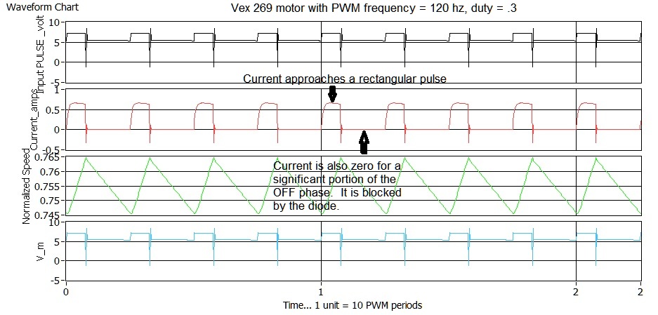
This curve was generated with a Labview program I wrote which is a simple integration of the L R response to various duty cycle inputs.

X  Vamfun triangular approximation        lamda <<1     ,  D’ = 1 – D

This approximation occurs when the PWM frequency is much higher than the motor response frequency and many PWM cycles occur in one tau for the motor.    Both the ON and OFF phase waveforms are approximated by linear slopes and the waveform is triangular.     The approximate formula becomes

i_avg = (V_b – V_bemf)*D/R  – (V_d + V_bemf )*(1-D)/R   or collecting D terms

i_avg = (V_b +V_d)*D/R  – (V_d + V_bemf)/R 

This leads to a linear steady state speed vs duty  when i_avg = i_free.   I. E.

V_bemf(steady state) =  (V_b + V_d) *D    –  i_free*R  – V_d   

for  D    >  (i_avg*R  + V_d)/(V_b  +V_d)

else

V_bemf = 0.

This equation  becomes  the standard DC motor current model when V_d = o .

This linear speed response would be typical of a Vex 269 being driven by a TI  JAGUAR  controller  that operates with a PWM frequency of 15 kHz which makes lamda = .24 .  The JAGUAR controller is used in First robotic competitions.  It  produces  a typical triangular waveform as shown here (click to expand figure):

XI  Non extreme lamda produces exponential saw tooth:

This figure shows an example of an exponential saw tooth waveform produced by Vex controller (PWM frequency 1250 hz , lamda = 3) driving a Vex 269 motor with a .3 duty.      (click to expand)

Notice that the first trace which is the motor voltage has three distinct levels.  During the ON phase it equals V_b.  During the off phase while the diode is conducting it equals       -V_d and when the current goes to zero it then  reads the back emf voltage V_bemf.   During this period some controllers actually sample V_bemf to estimate motor speed without encoders.  If the diode always conducts like the previous figure, then the controller must periodically use a special pulse to sample V_bemf.

XII Computational Proceedure:

Ok, we have lots of formulas and here are the steps to put them to use.

0) Gather inputs: V_b,V_bemf,V_d, lamda, R, command

1) Compute the input duty D and direction dir

D = abs(command/127)

dir = sign(command)

2) Compute  i_ss_on and i_ss_off from known voltages.

i_ss_on = (V_b*dir – V_bemf)/R

i_ss_off = -(V_d*dir + V_bemf)/R

3) Compute i_0 and test if current is continuous or discontinuous.

i_0 = ( i_ss_on*(1 – exp(-lamda*D))*exp (-lamda*(1-D))+ i_ss_off*(1 – exp(-lamda*1-D)))/(1 – exp(-lamda*D)*exp(-lamda*(1-D)))

If the sign(i_0) is opposite the sign (i_ss_on).   I.e.

if( sign(i_0) *sign(i_ss_on) < 0 ) then  current is discontinuous and  set i_o = 0.

4)  Compute i_max

i_max = i_o*exp(-lamda*D) + i_ss_on*(1 – exp(-lamda*D))

5) Compute D’

if(discontinuous) then

D’    =  – ln( -i_ss_off/(i_max – i_ss_off)* lamda)

else

D’ = 1-D 

6) Compute i_avg

i_avg = i_ss_on*D + i_ss_off*D’

Thats it.   See link below for a RobotC implementation of these equations.

Related Links:

Vex 269 Current data based upon Excel Hbridge Model

proposed-method-of-incorporating-ptc-resistance-into-my-vex-motor-models/RobotC subroutine to compute Vex 269 motor currents

smart-software-monitor-keeps-ptc-fuses-from-tripping

Vex threads:

Estimating 269 Motor Current based on H bridge models

Estimating motor current

RobotC subroutine to compute Vex 269 motor currents

July 14, 2012

I have written a subroutine that implements the excel H bridge model equations in robotC.   I have not checked the computational time of the routine but it should be ok.  The program can be down loaded from here.  The program uses the exp() and log() features of RobotC.   It is a function that has a prototype like this:

float current_calc_269( float rpm, float cmd ,float v_battery) {

//subroutine written by Vamfun…Mentor Vex 1508, 599.

//7.13.2012  vamfun@yahoo.com… blog info  https://vamfun.wordpress.com

//Vex motor 269 assumed

// inputs:  rpm, motor speed in rpm  Note:***Program assumes that with positive command, rpm is positive.***

//          cmd, motor command [127 ,-127]

//          v_battery, average battery voltage >0

// Output:  i_bar ,average motor current per PWM cycle in amps

……

}


Estimating moment of inertia for Vex 269 and 393 motors

July 12, 2012

Jpearman has done some great lab testing with Vex motors.  This post shows the motor current response for both 269 and 393 motors to a step response.   The steady state is achieved in around 100ms for both motors.

Good data.   It appears that both motors have a time constant tau = 20 ms based upon the initial slope or using 100ms as a 5*tau value.

We can use this data to calculate the approximate moment of inertias of the motors.    Since the motor time constant  tau = max speed/max accel  and the max speed is the same for both motors … we know that the motor max accelerations are identical for both motors.    Since max speed = 10.4 rad/s   and max accel = stall torque/Izz   we can calculate Izz for a 269  as

Izz_269  = tau*stall torque/max speed  = 2.8 in_lb*.113 nm/in_lb*tau/10.4  = 6.085*E-4 kgm^2

Using the equality of motor max accelerations gives a  ratio to get  Izz_393  from Izz_269  and the motor torques.  So

Izz_393 = Izz_269*Istall_393/Istall_269 = 6.085E-4*14.7/2.8 =  3.19E-3 kgm^2

So we now have enough data to do a pretty good motor model.


Note: Minimum Motor Torque for Turning

November 23, 2011

I wanted to do a quick calculation for a student Vex robot that has 5 in wheels and is having one rail stalling during a turn.    The stalling could have been predicted with some basic torque calculations.

Using static moment equations you can easily derive the minimum torque to just turn  for a symmetric robot with four direct drive  motors on wheels with radius r .  Legacy three-wire 6.5 inlb motors are assumed.

Define the half spacing between axles as “l” and the half width between wheels as “w”   , the robot weight as W_lbs and the coefficient of friction for a tire side force as u.  Also assume that the weight is evenly distributed on the four wheels and the center of turn is at the cg.  Also w > l so turning can occur.

Then

Input turning moment per wheel = w* torque/r and this must be greater than the moment resisting the turn caused by the side friction forces on the wheel.

Resistance moment = l*W_lb*u/4  .    The factor of 4 converts the W_lbs to normal force on the wheel.

So torque > r*(l/w)*W_lb*u/4

Lets plug in some typical numbers.  r = 2.5 in, l=3.5, w = 7

This gives a required motor torque of  2.5*3.5/7/4*W_lbs*u

or torque >( 2.5/8) * W_lbs* u

or W_lbs <  torque*8/2.5/u

Without omni wheels, u is typically  around 1 or higher and if the robot W_lb is 12 lbs  then the minimum torque

torque_min > 3.75 in lbs

This represents about 60% of the old three wire motors 6.5 in lb  spec torque .       Clearly there is not much margin for any torque losses in the drive train or extra side friction on the wheels or extra weight from a heaver robot or from game objects.  Also any contact forces resisting the turn will easily stall the turn.

Using a 4 in omni wheel in place of the 5 in traction wheels increases the input torque by  5/4 and reduces the u by about 1/3   so we get a combined improvement of  15/4 or 3.75 factor on the required torque.

min_torque_ 4 in omni =  3.75 / 3.75 = 1 in lb or about 15% of the available torque of an old motor.   This is where you want to be in your design.


Note: Adding some braking to the move_encoder(.) function

November 5, 2010

Most of the 599 teams are using gear ratios that increase speed and decrease motor drag force.    As a result, the move_encoder(…) function provides a lot of overshoot due to the robot momentum since it is not a PID loop.    Typically, a 24 in/s top speed can produce 6 to 9 in of overshoot.  So we need some braking that is also adjustable.  I will do a few calculations to estimate how long it takes a typical robot to slow down from the max speed when given a full reverse command.   The best way is to measure the deceleration response, however,  it can be estimated analytically by using  some assumed dynamics for the robot/motor system.

Analysis:

Robot assumptios:

wt = 10lb

max_tq = 26 inlb (2 393 motors per side with 13 inlb per side )

gr = 84/60= 7/5  (wheel speed to motor speed)

g = 12*32.2= 386.4 in/s/s  (gravity)

r_in = 2.  ( wheel radius)

max_accel = g*max_tq/(gr*r_in*wt) = 359 in/s/s or roughly 0.9 g’s

max_speed = 100rpm*2pi/60*gr*r_in= 29.3  in/s

tau = max_speed/max_accel =  .081 sec  (motor time constant)

Assuming that the motor is a first order lag,  the speed response  to a step reverse command  input  of  (v_0 – v_final)  follows the equation

v =  v_final + (v_0 -v_final)*exp(-t/tau)

where v_0 is the initial speed and v_final is the final steady state speed.

Here , v_0 = max_speed and v_final = -max_speed  and we want to solve for t that makes v= 0.

So substituting and solving for t

exp(-t/tau) = -v_final/(v_0-v_final)   or

t = -tau*ln(.5) = .69*tau

Thus the time to drop the speed to zero is   t =  .69*.081 = .056 sec

The average speed over this period is about max_speed/2 so the

stopping_dist  ~= max_speed*t/2= 29.3*.056/2 = .85 in

Discussion:

The robot can decelerate from max speed to zero speed in less than .06 sec  and  the over shoot should be less than .85 in.     We know that a heavier robot, e.g. 20 lbs , will have twice the tau, hence  for design purposes, I’ll assume  a max reverse brake command  with a nominal .1 second pulse and make the pulse duration adjustable  to accommodate different weight robots.    We can add enough time for the robot to back-up and have zero overshoot.     This tweeking  can also be done automatically by a PID controller with a high gain but the timed pulse technique  has the advantage of a minimum time controller since it uses maximum command rather than proportional commands.   The PID approach  will be a topic of future discussions.

The max_acceleration did not take in to account the dynamic friction of the drive train and we would expect the actual robot to slow a little faster since the 393 motors have about 1 inlb of drag torque.

Braking software code:

We require a parametric timed pulse (nominally .1 sec) of max motor reverse command (127).   A timer is needed to put in a signed pulse after the distance goal has been crossed in the Move_encoder (..) code.    When using Move_encoder(..) we would just set the goal distance and then tweek the brake time to minimize the overshoot without reversing.

If pwm_brake = o then braking calculations can be bypassed and the robot is free to coast with just motor drag to slow it.

Move_encoder(..)  with braking changes might look like this:

UPDATED 12/5 to add b_brake_done logic to keep output latched when using Move_encoder with other utility functions in the same step. Changed the name to Move_&brake_encoder(..)

int Move_&brake_encoder(int goal , int pwm_input , int brake_time10 = 10)
{
// test routine similar to what might be used for encoders
// goal is the incremental distance you want to go from where you are
// goal is + or – relative distance in dist_10in units (deci inches)
// brake_time10 is the reverse motor brake pulse time in hundredths of a sec
// pwm_fwd , dist_10in , bsys_reset, bauto_move are global
static int target_dist = 0;
static int target_time = 0;
static bool b_move_done = false;

static bool b_brake_done = false;
if(bsys_reset)
{
//initialize stuff for output
bauto_move = true; // take control of the motors that are used in this function
target_dist = dist_10in+goal; //compute goal in reference axis units.  Input goal is relative to where you are
if(goal<0)
{
pwm_fwd = -pwm_input;//move in direction of goal
}

else
{
pwm_fwd = pwm_input;
pwm_brake = -pwm_brake; //need to reverse brake sign
}
b_move_done = false;

b_brake_done = false;
return 0;
}
else
{
if( (goal<0 && dist_10in > target_dist || goal>0 && dist_10in < target_dist )&& !b_move_done) return 0;
else
{

// start braking
if(!b_move_done)
{
target_time = time10[T1] + brake_time10;
b_move_done = true; // keeps the target_time from being reset while we wait
pwm_fwd = pwm_brake; //brake in direction opposite of goal
}

else if(time10[T1]< target_time && brake_time10  !=0 && !b_brake_done) return 0; // wait for braking
else
{//done braking so exit

b_brake_done = true;

bauto_move = false; //return control to joystick
pwm_fwd = 0 ; //set the speed to zero again
return 1;// sets done = 1
}
}

}
}