Nothing but Net 2015/2016 competition game involves shooting 4 inch balls that can have a 10% variation in mass. We know that trajectory range ,R = V^2/g*sin(2*theta) so it is dependent upon the square of the ball release speed , V, and shooter elevation, theta. Mass does not enter into the equation unless it affects V.
Ball release energy :
Suppose we use a Vex 5″ diameter wheel as a flywheel and rotate it a w_wheel angular speed. As the ball leaves the shooter, it will have a V = r_wheel*w_wheel/2. e.g. half of the flywheel tangential speed. The ball will have a spin rate , w_ball = V/r_ball. The energy of the ball, E_b , is the sum of the ball translational energy and rotational energy.
E_b = 1/2*m_ball*V^2 + 1/2*I_ball*w_ball^2
where I_ball = 2/5*m_ball*r_ball^2 (solid sphere of uniform density).
so Eb = 1/2*m_ball*V^2( 1+2/5) . (corrected 5/29 Was 1/2*m_ball*V^2( 1+4/5) So the rotational energy adds 40% more to the translational energy. Rewriting in terms of w_ball gives
E_b = .7*m_ball*w_ball^2*r_ball^2
Wheel Energy:
E_wheel = .5*I_wheel*w_wheel^2. where
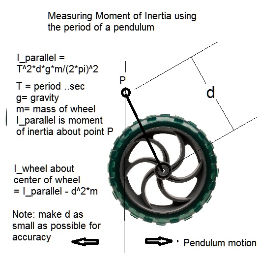
I_wheel = m_wheel*(r_wheel*.84)^2 (ref blog post https://vamfun.wordpress.com/2015/05/17/finding-the-moment-of-inertia-of-a-vex-wheel-using-parallel-axis-theorem/)
Energy Conservation:
E_wheel_initial = E_wheel_final + E_ball This assumes that the wheel is not being powered by the motor during launch and that the extra energy needed for the ball comes from the flywheel. Also, friction and ball compression energy losses are assumed zero to simplify this analysis but can be significant in actual percentages derived. I am focusing on how increasing flywheel mass lowers the percentage range errors caused by ball mass variations.
E_wheel_initial/E_wheel_final = (1 + E_ball/E_wheel_final)
Lets expand E_ball/E_wheel_final
E_ball/E_wheel_final = (.7*m_ball*w_ball^2*r_ball^2)/(.5*I_wheel*w_wheel_final^2)
= 1.4*m_ball*w_ball^2*r_ball^2/(m_wheel*r_wheel^2*.84^2*(2*w_ball*r_ball/r_wheel)^2)
= .4954*m_ball/m_wheel
SInce m_ball = 60 g and m_wheel = 180 g m
_ball/m_wheel = 1/3
So E_ball/E_wheel_final = .165 for a single 5″ wheel flywheel .165/n for n flywheels. So the ball energy is almost equal to the 1/6 final energy of the wheel
Range Tolerance analysis:
So how does R vary with m_ball from all this. Well , we know the range is proportional to V^2 which is proportional to w_wheel_final^2 which is proportional to E_wheel_final.
From above E_wheel_final = E_wheel_initial/(1+ .4954*m_ball/m_wheel)
So due to proportionality of R and E_wheel_final we can say
R/R_0 = ((1+ .4954*m_ball_0/m_wheel)/(1+ .4954*m_ball/m_wheel))
where R_0 and m_ball_0 are the nominal values without errors.
We can use R range= R_0(1+ %e_r) and m_ball = m_ball_0*(1 + %e_m_ball) to work with % changes.
Then with some manipulation we can get %e_r as a function of %e_m_ball
%e_r = -%e_m_ball/(2.02*m_wheel/m_ball_0 +1 + %e_m_ball)
Now m_wheel = n*.180 kg and m_ball= .06 kg so we can write an approx.
%e_r = -%e_m_ball /( n*6.06 +1) where n is the number of 5″ vex wheels.
Lets put in a few numbers:
Assume %e_m_ball = 10% then the range error is
n = 1, %e_r = -1.42%
n = 2, %e_r = -.76%
n = 3, %e_r = -.52%
n = 4, %e_r = -.40%
n = 5, %e_r = -.32%
So you see the benefits of having a higher flywheel mass to ball mass ratio. The use of two 5″ wheels in a single wheel design can reduce a potential 10% range error from ball mass variations to 1% ( less than a ball radius). To keep the spin up time to a reasonable number of seconds requires about 2 393 motors per wheel so 2 wheels costs 4 motors. So there is a motor tradeoff to get that higher accuracy with heavier flywheels.


 Posted by vamfun