Compensation for gravity induced error offsets using feedfoward inputs to arm joint motor PID controllers
If an arm joint has a torque induced by the weight of the arm or other loads under steady state conditions the motor must hold a constant counter torque . This torque requires a small constant current which in turn needs steady input command, delta. The motor controller usually contains a PID function which must hold the motor command . If we assume that Kd amd Ki are zero (for most controllers) then the command is held either by a feedforward input or and angle error equal to delta/Kp where Kp is the position feedback gain.
If the max command amplitude to the motor is scaled to 1 then we can compute
delta = -torque_gravity/(torque_stall*gr)
The minus means it is fed opposite to cancel the gravity torque.
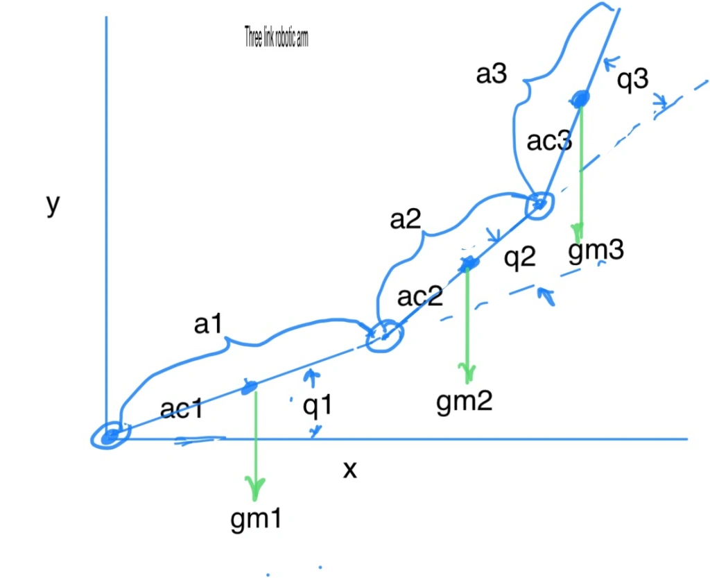
gr is the motor gear ratio and torque_stall is the motor stall torque. Torque_gravity can be derived from the inverse kinematics for the center of masses on the links. For a three link arm the equations for each joint are :

G(1)=g*(c1*(m1*ac1 + m2*a1 + m3*a1) + c12*(m2*ac2 + m3*a2) + c123*m3*ac3);
G(2)=g*((m2*ac2 + m3*a2)*c12 + m3*ac3*c123);
G(3)=g*m3*ac3*c123 ;
G(1),G(2) and G(3) are the downward gravitational induced torques at each joint.
q1,q2,q3 are joint angles
m1,m2,m3 are arm masses
a1,a2,a3 are link lengths
ac1,ac2,ac3 are link cg lengths from joint
g is acceleration due to gravity.
%sin and cos of angles
c1=cos(q1)
c2=cos(q2)
c3=cos(q3);
c12=cos(q1 + q2);
c23=cos(q2 + q3);
c123=cos(q1 + q2 + q3);
Since we have h torque_gravity and we then calculate the delta for each joint.. e.g. for joint 1
delta_1 = -G(1)/torque_stall_1*gr_1
If feed forward is used delta is fed directly to motor with a gain of 1.
If no feed forward then the motor command must be held by a q1 error = -delta_1/Kp