Making Fat Shark FPV goggles work with OPENROV ($7 solution ?)

March 7, 2014

Robodox ROV team is building an OPENROV 2.5 kit for Algalita Research Foundation to take on their July 2014 Pacific Gyre expedition.    The ORV catamaran , named Alguita, will take a team of scientist to sample and analyze the effects of plastic in the ocean on marine species.    To help extend their capability to locate plastic concentrations they are utilizing a variety of sensors.   One is a Phantom quadcopter drone equipped with a Fat Shark Predator V2 FPV system.

IMG_7776The Predator V2 uses two LCD screens to display video in goggles show below.

IMG_7783

The Predator specifications are shown here.   Pictures are sent from an aerial camera platform to the goggles in real time over a 5GHz wireless link.

openrov 2.4The underwater ROV that Robodox is building will do a similar function by transmitting HD camera video to a topside Laptop computer over a two wire tether.    It would be desirable if the Fat Shark video goggles could also display the Laptop video sent by the ROV.    Unfortunately the video formats are not compatible without a VGA to composite video converter.   I did a little research into how this could be accomplished.

Here is the plan:

1) purchase a Tmart $3  VGA to A/V RCA converter.  03m-VGA-to-SVIDEO-and-RCA-Female-Cable_320x320

2) Purchase an $3.50 Allelectronics 3.5mm  A/V  to RCA cable with 6 ft  extension to allow freedom of movement between the laptop and the goggles.

3) Plug the VGA converter into the laptop VGA output port and then plug the 3.5mm A/V cable into the Fat Shark video input port via the extension.   Turn off the Fat Shark wireless receiver.

Seems like this would work…yet to be tested.

Wireless Connection to the Fat Shark

The transmitter side of the Fat Shark FPV system involves a small 600 TVL camera that plugs into a transmitter compatible with the receiver in the goggles.

Fat Shark tranmitter

If the transmitter is available on the boat (ie a spare that is used for the Phantom drone) then the output of the converter could be used in place of the camera output that plugs into the transmitter.   This way the goggles could be free from any wires. There would be another plug adapter to mate the composite video RCA plug to the plug on the xmitter.


Algalita OPENROV ready for testing

February 25, 2014


I wanted to share what the Robodox Algalita ROV engineering team has been up to for the last two months.  See Robodox Engineering ROV for ORV blog post : Feburary Status Update .   I am happy with their progress and we expect to have the underwater robot ready for the Algalita summer voyage.

Relevant posts:

Dec 20 2013 OpenROV Berkeley Trip

Robodox 599 Algalita 2014 Youth Summit Video Submission

Use of Robotics to support Algalita research into the Pacific garbage patch

Links:

http://robodoxrov.wordpress.com (build blog)

Algalita ROV project facebook page


Robodox 599 Algalita 2014 Youth Summit Video Submission

October 30, 2013

http://www.youtube.com/watch?v=CnxKUEi1mJQ


note 1 Beaglebone Black: Boot attempt using OPENROV image

August 9, 2013

As mentioned in my last Arduino post, the 599 Algilita ROV team selected the OPENROV processing architecture for their ROV.   It was hoped that this would save us a lot of time setting up the cockpit display software which is already working on OPENROV.   Ha…think again.   Unfortunately, the OPENROV flash image which works so nice in the Beaglebone doesn’t seem to boot with the Beaglebone Black (BBB), at least for me.

Flashing the OPENROV image to BBB (unsuccessful)

The BBB uses a built-in eMMC to boot from normally.   To flash a new image you insert a micro SD MMC and while holding down the User (boot) button on the BBB you power up the board either by USB or 5v power supply.  Continue to hold the button until the user LED’s begin to blink (See flashing procedure),  The BBB board is then boots up and transfers the image from the micro SD to the built-in eMMC.

I made a bootable 8GB micro SD card using the Windows solution outlined in the Getting Started link  github.com/OpenROV/openrov-image.   I held the boot button down, powered up and waited for over 5 minutes for the user LED’s to light, but only the power LED lit.

I searched the forums and only found one comment re the BBB not being able to flash the OPENROV-image.  Apparently some modifications need to be made to the uSD 64K partition that contains a file called

I did check that I could flash something by starting with a fresh Angstrom image and booted that ok.


note 2 BeagleBone Black:building OpenROV software with Angstrom

August 9, 2013

I decided to try to get the OpenROV software working using the demo Angstrom distribution that comes installed in the BBB since it has a lot of the needed packages already installed and you don’t need an Ubuntu SD image.   There are 13 installation steps in the OpenROV/openrov-software/Readme.md file shown here.  I skipped step 1 since I am using Angstrom.  I postponed Step 2 for later if I get everything else working.

Step 3

upgrade software and install rerequisits (holy moly, there’re packages!):

sudo apt-get update
sudo apt-get install g++ curl pkg-config libv4l-dev libjpeg-dev build-essential libssl-dev vim cmake

I verified that most of the required packages were already installed and found only “build-essentials” missing from Angstrom.  Those that were installed were updated with opkg.

build-essentials was not found in searching Angstrom opkg.   However,  I did find packagegroup-core-buildessential-dev 1.0-r0.1 .  I installed this with opkg and seemed to work.

Installing SUDO:

Using opkg search I couldn’t find  a sudo package.  I did find an Angstrom dev package for sudo and installed that by downloading it to my computer from here and copying it to the BBB root.   I then used

root:/# opkg install ./sudo_1.8.4p4-r1_armv7a.ipk

The program unzipped the ipk package and successfully installed  sudo.

Step 4:

Install nvm (Node Version Manager):

git clone git://github.com/creationix/nvm.git ~/.nvm
echo ". ~/.nvm/nvm.sh" >> .bashrc
echo "export LD_LIBRARY_PATH=/usr/local/lib" >> .bashrc
echo "export PATH=$PATH:/opt/node/bin" >> .bashrc

And make those changes work now:

source ~/.bashrc

I followed these instructions and tried to install node v0.8.11 as per Steps 5 thru 7  but ran into a missing Python compiler.ast error so I opkg updated the Python compiler and then things worked.   Since Angstrom has v0.8.2 node installed already, I don’t think it is necessary to install v0.8.11 but I have yet to try this.

No /opt/ directory

It seems that my Angstrom dist doesn’t have an opt directory and I am not sure why since it is standard in the LInux directory tree.  Also many of the paths in OpenROV software assume it is populated.   My solution was to create the directory.   Later I would install OpenROV software into it.

Step 8

Install mjpg-streamer

Download mjpg-stream:

 wget http://downloads.sourceforge.net/project/mjpg-streamer/mjpg-streamer/Sourcecode/mjpg-streamer-r63.tar.gz

Prepare mjpg-streamer for make:

tar zxf mjpg-streamer-r63.tar.gz
cd mjpg-streamer-r63.tar.gz

Make and install OpenCV:

make && sudo make install

The r63.tar.gz package would not install because of  fatal error: videodev.h No such file or directory .   Apparently it uses videodev.h instead of videodev2.h which is in more recent library distributions of Linux..at least in my version of Angstrom.  I tried to fix it by just changing all the videodev.h to videodev2.h in all the source files that need it.  I got it to compile through most of the files but ran into some other problem which I don’t recall right now.   So I gave up and found a more recent version of mjpg-streamer on the github.com site that uses vidodev2.h.  You can download this from Dominik’s codewithpassion site as “mjpg-streamer or the sourceforge site that it is branched from.  You know you have the right version if mjpg_streamer.c has <linux/vidoedev2.h>.

I actually installed mjpeg-streamer-experimental in /root rather than /~ and tested it standalone and it seems to work fine with Chrome except there is about .5 second delay in the image.  I understand that the delay is roughly .2 to .3 seconds with Firefox browser but I didn’t try it.

Step 9 Download OpenROV ROVision:

cd ~
git clone git://github.com/OpenROV/openrov-software.git
cd openrov-software/

Change to development branch:

git checkout development

edit ~/.bashrc, add:

export LD_LIBRARY_PATH=/usr/local/lib

You’ll need to restart your shell:

source ~/.bashrc

Git OpenROV-software

Ok I did all this but I could not checkout development branch…it said that it didn’t exist.  I decided to use Dominiks codewithpassion/OPENROV code since it probably was more recent and also had a development branch which I checked out to 599ROV branch.

git clone git://github.com/codewithpassion/openrov-software/

git checkout remote/origin/development -b 599ROV

Step 10

Download modules:

npm install express socket.io serialport

Completed this step ok and had enough modules to start testing.  I did this from root directory.

Preliminary tests:

Restarted shell with

source  ~/.bashrc

node app

and got error that “forever-monitor’ module could not be found.   This is located in node.   I fixed this by reinstalling node in root rather than home.  The is is because the openrov software is now installed in /opt  I think.

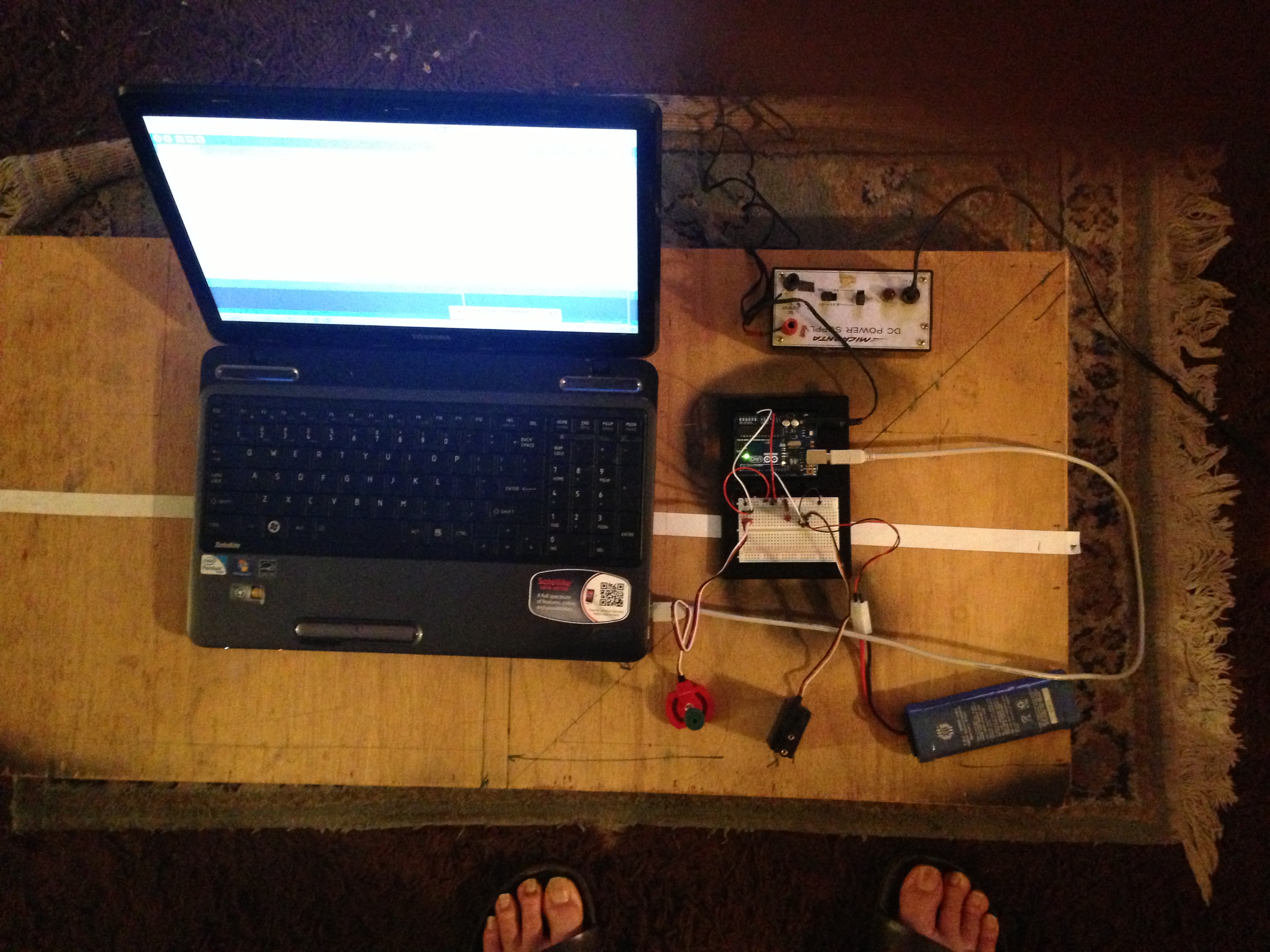
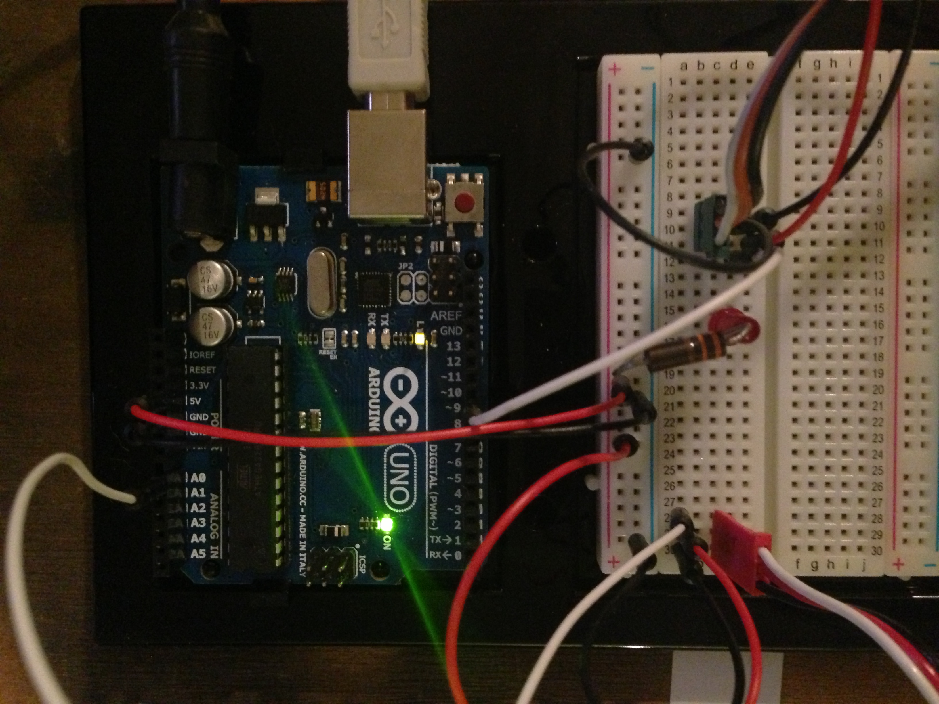
Cockpit display now works and includes the Genius camera image!!

The next note will be on getting the Arduino firmware loaded to the OPENROV Cape.


Getting my feet wet with Arduino Uno

July 18, 2013

Arduino Uno

I have tried to stay away from Arduino mainly because I didn’t want to learn a whole new culture. However, my AlgalitaROV project uses the OPENROV electronic architecture which employs a Cape that uses the Arduino Uno processor which in turn attaches to a BeagleBone Black(rats…another processor culture to learn).
Downloaded and installed the Arduino SDK 1.0.5 from arduino.cc and read through the getting started and reviewed the types of commands it uses. I bought a Arduino Uno starter kit from amazon ($32) which has a breadboard and some jumper wires. plugged in the Arduino Uno and it installed automatically without updating the drivers as suggested in the instructions. First observations:

1) the general purpose I/O (GPIO) are 5 volt at the breakouts. This is great since it is compatible with Vex parts. Current is o limited to 40ma per pin.

2) it can be powered from the USB cable or an external supply that must range from 6v to 20v with a recommendation of 7v to 12v.

3) Software wise in the Arduino you write a void setup() function and a void loop() function. These functions are called automatically by the operating system. setup() runs once and the loop() runs continuously…meaning the hidden main() function contains a while(true){loop()} structure that runs after the setup() runs. By contrast the Vex RobotC template calls a function pre_autonomous() once and executes separate tasks autonomous() and usercontrol(). usercontrol contains an explicit while(true){} which the programmer can change. Not sure that Arduino gives us that capability.

3)There are plenty of software examples and the language is close to C. The only function that seemed misnamed was analogWrite(pin,duty). This doesn’t write an analog output to a d/a hardware as one might assume but puts a 5 volt PWM signal output on a PWM capable GPIO pins. On the Uno 6 of the 14 GPIO pins are PWM capable (3,5,6,9,10,11). Not sure why they didn’t just call it PWMWrite().

4)Servo library is available for use but be careful with servo.write(int val).

Here is the function code from the servo library.  Note that if val is >544 then the command is assumed to be in microseconds rather than servo degrees.  Also note if it is less than 544 that the degree values are truncated to valid servo range of [0,180].    So a val = 255 will produce a 180 degree command.

void Servo::write(int value)
{
  if(value < MIN_PULSE_WIDTH)
  {  // treat values less than 544 as angles in degrees (valid values in microseconds are handled as microseconds)
    if(value < 0) value = 0;
    if(value > 180) value = 180;
    value = map(value, 0, 180, SERVO_MIN(),  SERVO_MAX());
  }
  this->writeMicroseconds(value);
}

First Script.
We need an r/c brushless motor driver. The ESC needs a standard servo drive signal. So I hooked up a Vex pot to the board and read its value [0, 1023] and scaled it to [0,180] which is given to a canned servo program object which has a servo.write which generates the proper servo output to a specified pin.  A motor is a continuous rotation servo  so 0 value represents max reverse speed and 180 value gives max forward speed.   I also included a serial printout of the value to the laptop console.
Hardware Setup:
[click on picture to expand to full size]

Shows breadboard wiring , motor 7.2v battery and external board 5 volt power supply

Shows breadboard wiring , motor 7.2v battery and external board 5 volt power supply

It is important to note that the motor is powered by a separate battery since it draws more current than the board can supply.

Closeup of arduino wiring

Closeup of arduino wiring

Full test setup

Full test setup

Mymotorcontrol.ino

// Controlling a servo/motor position using a potentiometer (variable resistor) 
// by Chris Siegert:  vamfun@yahoo.com   https://vamfun.wordpress.com
// adapted from  Michal Rinott servo code  
// connect the center pin of a potentiometer (pot) to the potpin.  Connect the other two pins to the arduino 5v and ground pins.
// connect the white wire of the motor pwm cable to the servopin.  
// Important!! Connect the red and black wires to an external motor power source. 
// The arduino is not designed to deliver enough current to drive a servo/motor.
#include <Servo.h> 

Servo myservo;  // create servo object to control a servo or motor. 
int servopin = 9; //connects servo to pin 9 which is a pwm pin.
int potpin = 0;  // analog pin A0 used to connect the potentiometer
int val;    // variable to read the value from the analog pin 
int cmd = 0; // cmd to motor [0 to 180]
int cnt = 0; // program cycle counter 
int cnt_max = 33;   // this is the number of delay cycles between serial printouts. (15ms per cnt) 33 counts gives about 2 per second)  
void setup() 
{ 
  Serial.begin(9600);   //start up the serial data port at 9600 baud 
  myservo.attach(servopin);  // attaches the servo on servopin number to the servo object void loop() 
{ 
  val = analogRead(potpin);            // reads the value of the potentiometer (value between 0 and 1023) 
  cmd = map(val, 0, 1023, 0, 180);     // scale it in degrees of servo rotation(value between 0 and 180) 

  myservo.write(cmd);                  // sets the servo position according to the scaled value in deg 
  cnt++; 
  if(cnt > cnt_max)                  // this sets time between serial print outs to cnt_max cycles  or about (15 ms*cnt_max)
  {
    Serial.println(cmd);  
    cnt = 0;      // debug value
  }
  delay(15);                           // waits for the servo to get there 
}