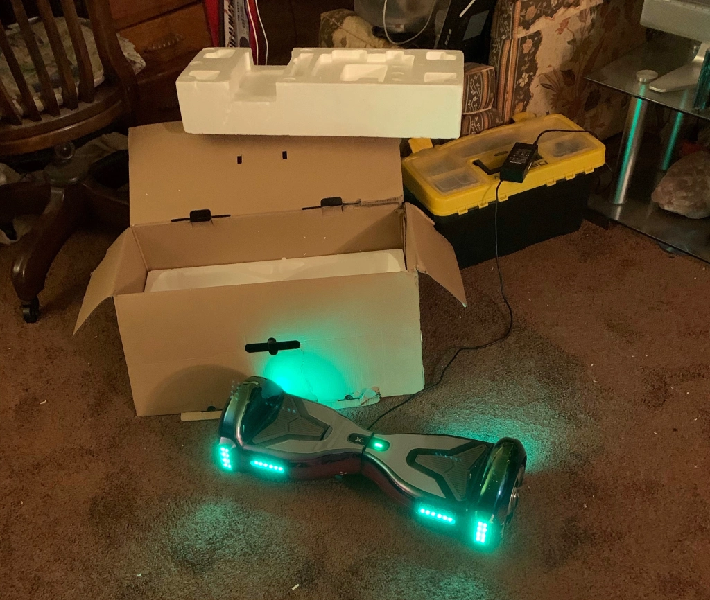
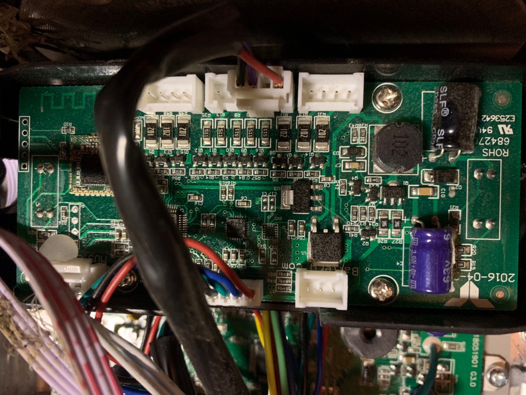
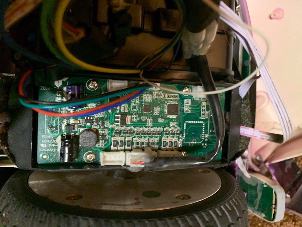
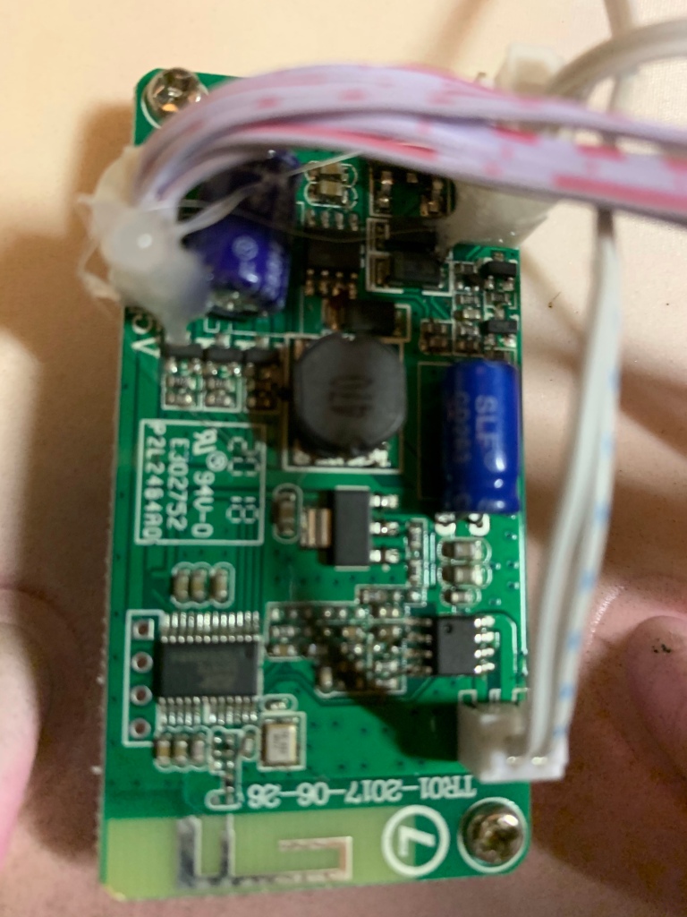
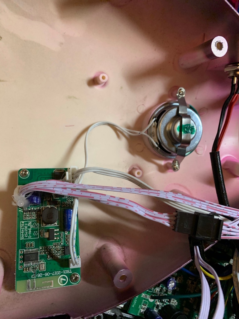
Flying Fire Hose blog #1. Hover-1 H1 Hoverboard tear down

December 23, 2020

New project underway….to robotically fly a fire hose with dual water jets attached using a hoverboard hack.

Hover-1 H1 specs. https://hover-1.com/hover1-h1-specs

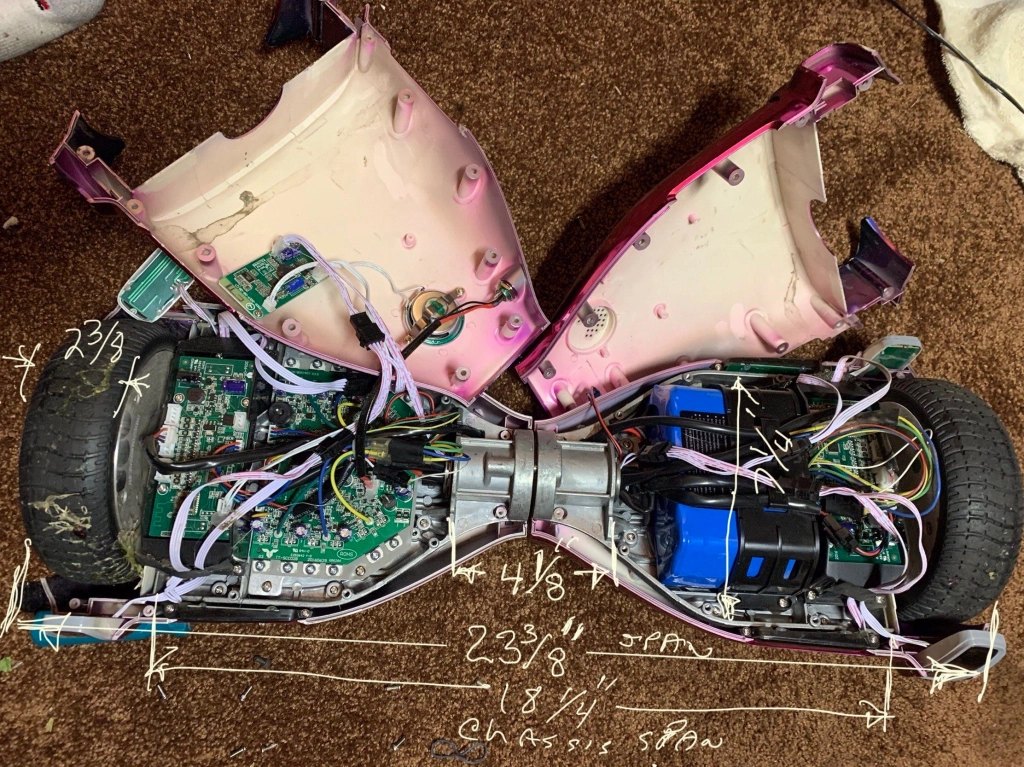
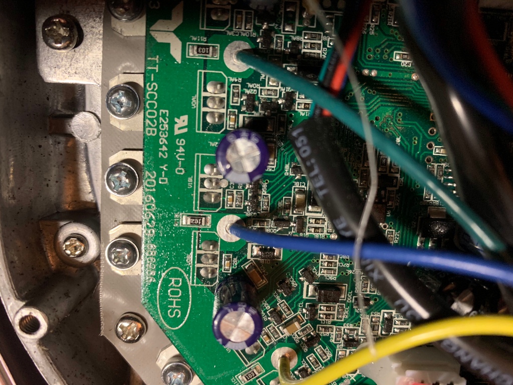
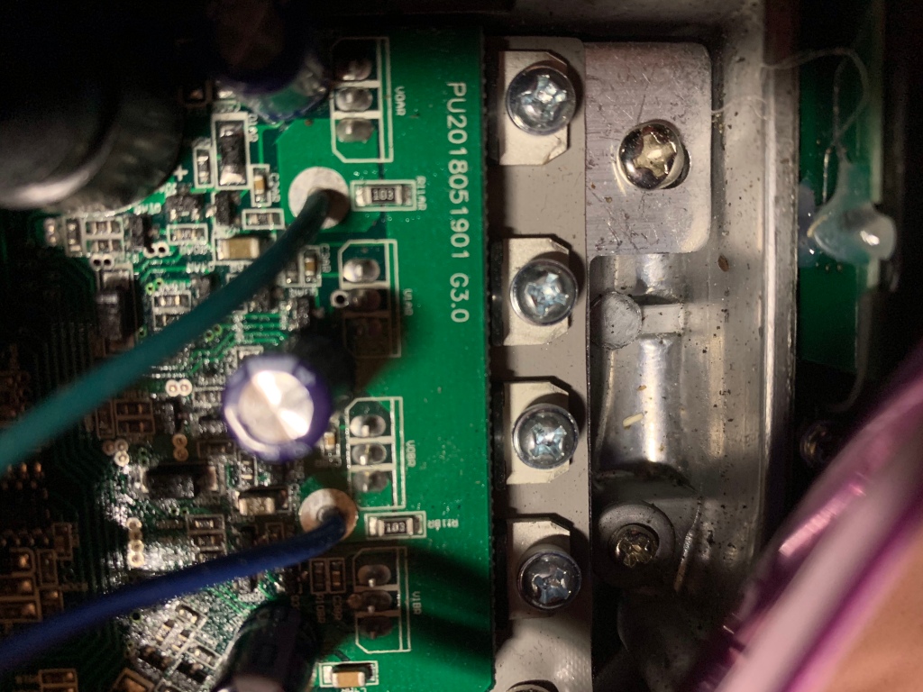
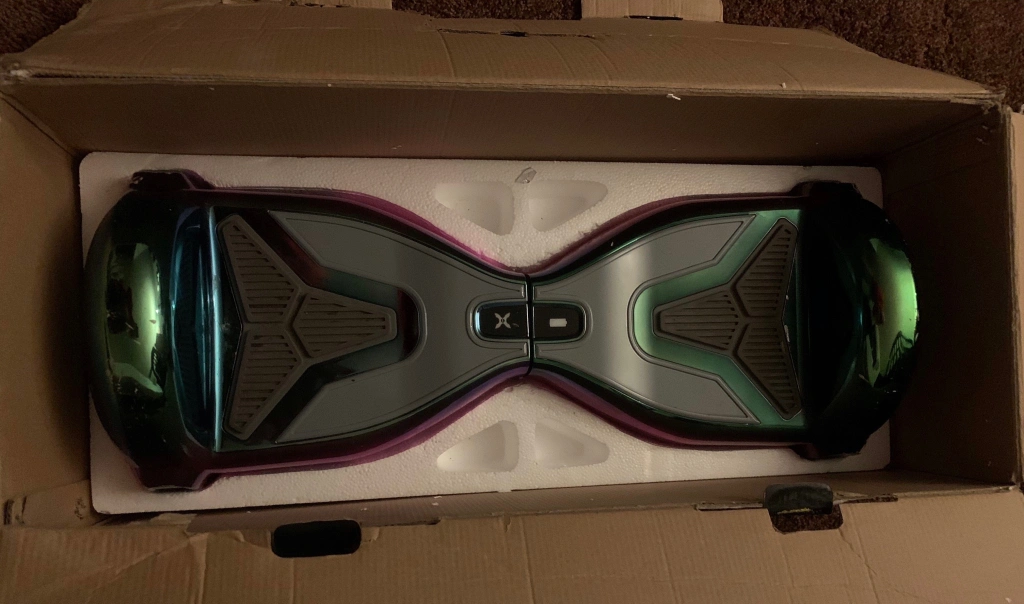
Here is a look inside with a few dimensions. Bought used..smell of burnt electronics but handles nicely. Around the house uses about 1% to 2 % of battery per minute according to Bluetooth app.


OpenROV Cape Test Program (No Beaglebone required)

November 30, 2013

I decided to modify the OpenROV 2.4 Arduino source code to create an automatic test program that stimulates each of the cape outputs periodically to see if the Arduino ATmega328 chip and connecting circuitry are operating correctly.  Software has been tested with the cape operating  stand alone.  Hopefully it will run in a OpenROV cape with a Beaglebone attached provided the cape.(TBD)

Hardware Requirements:

OpenROV cape

Servo

LED lights

Battery Pack (12v)

ATmega328 programmer (Arduino Uno will do)

Proceedure:

1) Remove the ATmeta328 chip from the Cape and use an Arduino board to load the Openrov_cape_test.ino with includes.

2)Place the ATmega328 chip back into the Cape and hook up the externals (motors, servo and lights) .

3) Connect the battery power to the Cape. (Typically 12v)

4) Watch motors , servo and light cycle periodically in sequence. Each command level lasts for 2 seconds.

20131130-171808.jpg

Software Files: Download OpenROV_cape_test  folder from my dropbox. In it you will find the following OpenRov_cape_test.ino file.   Just use it instead of OpenRov.ino file.

/* OpenROV_cape_test  Written by Chris Siegert, 11.30.13 , vamfun@yahoo.com, https://vamfun.wordpress.com This program is designed to test the OpenROV Cape.  Program generates commands that cycles motors, tilt servo and lights sequentially.  No Beaglebone is required for the test. Power the cape using the battery input terminals and connect the output devices. All motors are cycled simultaneously with 2 second steps at magnitudes {135,90,45,90}. Motors are left in reset mode. Next the servo is commanded to {170,10,90}Basically full tilt up to full tilt down and back to neutral. The light goes to full brihtness then to half brightness and then off. The device sequencing is then repeated continuously. If running without the Beaglebone, load the sketch and its includes into the ATmega chip using an Arduino project board or programmer.  Then reinsert the chip back into the cape.   If running with the Beaglebone, one might be able to just upload the program using the OPENROV cockpit utility. */

#include <Servo.h>

#include <Arduino.h>

#include “Motors.h”

#include “Command.h”

#include “Device.h”

#include “Timer.h”

Motors motors(9, 10, 11);

Command cmd;

Device vout(“vout”, 0, vout.analog, vout.in);

Device light(“light”, 5, light.analog, light.out);

Timer time;

Servo tilt;   int array[MAX_ARGS];

int case_no=1;   void setup(){

Serial.begin(9600);

pinMode(13, OUTPUT);

tilt.attach(3);

motors.reset();

light.write(0);

time.reset();

delay(3000);//wait for ESC to calibrate }

void loop(){

switch ( case_no)   {

case 1:

Serial.print(“motor”);

Serial.print(”  mag = “);

Serial.println(135);

motors.go(135,135,135);

delay(2000); //cds  set step delay

Serial.print(“motor”);

Serial.print(”  mag = “);

Serial.println(“90”);

motors.go(90,90,90);

delay(2000);

Serial.print(“motor”);

Serial.print(”  mag = “);

Serial.println(“45”);

motors.go(45,45,45);

delay(2000);

Serial.print(“motor”);

Serial.print(”  mag = “);

Serial.println(“90”);

Serial.println();    //motors.reset();

motors.go(90,90,90);

case_no++;

break;

case 2:

Serial.print(“servo” );

Serial.print(”  mag = “);

Serial.println(“170”);

tilt.write(170);

delay(2000);

tilt.write(90);

Serial.print(“servo” );

Serial.print(”  mag = “);

Serial.println(“90”);

delay(2000);

Serial.print(“servo” );

Serial.print(”  mag = “);

Serial.println(“10”);

tilt.write(10);

delay(2000);

Serial.print(“servo” );

Serial.print(”  mag = “);

Serial.println(“90”);

Serial.println();

tilt.write(90);

case_no++;

break;

case 3:

Serial.print(“light” );

Serial.print(”  mag = “);

Serial.println(255);

light.write(255);

delay(2000);

Serial.print(“light” );

Serial.print(”  mag = “);

Serial.println(128);

light.write(128);

delay(2000);

Serial.print(“light” );

Serial.print(”  mag = “);

Serial.println(0);

Serial.println();

light.write(0);

case_no++;

break;

default:

case_no = 1;  //repeat sequence

} //end switch

}


Note 3 Beaglebone Black: Getting OpenROV software to load .hex file into Arduino

August 7, 2013

I tried to upload a new Arduino program to the OpenROV cape using the software routines and the procedure outlined here.   On the cockpit display you select setup and then select a program to upload.   This program is a tar or zip compression of the Arduino source files.   The tar file is automatically expanded and then an attempt is made to build the hex file required by the Cape Arduino processor for upload.   The program threw an error which I traced to Arduino “ino” command line toolkit  program not being installed on the BBB.   I attempted to load ino onto the BBB as described here but that failed since a setuptool file for Python was missing.   This was installed  using

cd /

opkg install python-setuptools

Next, I reran  /ino/make install and now it couldn’t find the file py.compile.  This file apparenty is used in later versions of Python.  Searching opkg angstrom packages I found  python-compile_2.7.2-r3.17_armv7a.ipk\ which was downloaded to my pc and ssh to BBB.  I then used opkg service to install  it:

cd /

opkg install python-compile_2.7.2-r3.17_armv7a.ipk

ino seemed to be installed without errors.  Now tried to upload an Arduino file and of course more problems arose.  Seems that the ino makefile puts some of ino Python libraries in the wrong folder and when the ino calls were made several library functions were not found.    A search showed up this post which discussed the libraries and one of the comments to the post said that installing ino with Python commands works.  So I reinstalled ino using

cd /ino

python setup.py install

At last success!!   I ran another upload and got a little further until more errors showed up.    Here is the log file output:

Received ‘arduinofirmware-startupload’ for file: OpenROV_arduino.zip file: undefined going to install the uploaded file: OpenROV_arduino.zip unpack: build dir is /tmp/tmp.klu0me4aEo

Archive:  /opt/openrov/src/temp/OpenROV_arduino.zip    creating: OpenROV/   inflating: OpenROV/Command.cpp   inflating: OpenROV/Command.h   inflating: OpenROV/Device.cpp   inflating: OpenROV/Device.h   inflating: OpenROV/Motors.cpp   inflating: OpenROV/Motors.h   inflating: OpenROV/OpenROV.ino   inflating: OpenROV/Timer.cpp   inflating: OpenROV/Timer.h

unziped /opt/openrov/src/temp/OpenROV_arduino.zip in /tmp/tmp.klu0me4aEo/src

Unpacked firmware file into Searching for Board description file (boards.txt) … FAILED Board description file (boards.txt) not found. Searched in following places:   – /usr/local/share/arduino/hardware/arduino   – /usr/share/arduino/hardware/arduino

Compiled firmware in directory Closing serial connection for firmware upload Setting up uploader

Searching for Board description file (boards.txt) … FAILED Board description file (boards.txt) not found. Searched in following places:   – /usr/local/share/arduino/hardware/arduino   – /usr/share/arduino/hardware/arduino

Initiating arduino reset

/opt/openrov/linux/reset.sh: line 18: /sys/kernel/debug/omap_mux/gpmc_ad0: No such file or directory

upload failed, trying again. Searching for Board description file (boards.txt) … FAILED Board description file (boards.txt) not found. Searched in following places: – /usr/local/share/arduino/hardware/arduino – /usr/sh are/arduino/hardware/arduino

Initiating arduino reset

So it can’t find the board description and it is missing sys/kernel/debug/omap_mux/gpmc_ad0.   Back later when I figure this out.

 Ok… I’m back.   The missing board .txt file indicates that I need to install the Arduino IDE.   Normally ino uses AVERDUDE to boot up files to the Arduino but this is not installed on BBB.  I I tried to opkg averdude but Angstrom doesn’t have that .  However, all these files are in the Arduino IDE.  So I downloaded the  linux Arduino .tgz from here and ssh it to my root. Then installed this way

cd /usr/share

tar -xzf /arduino-1.0.5-linux32.tgz

Cool, now I have board.txt and averdude.


I fixed the gpmc_ad0 error by updating rc.local to make use of the .dt0 file overlay files supplied with Angstrom for BBB which are located in /lib/firmware.   Basically, I commented any reference to omap_mux and add code to set up UART1.  I will write a more detailed post on how to do this.

Using .hex file instead of .tar file of source

Why not build the .tar file on the host PC and then ask the OpenROV software to just upload the .hex file to the Arduino?   First, it took me a while to find where the Arduino puts the IDE.  Some said that holding the shift key down while compiling will show the file.   This didn’t seem to work so I just searched for the project name in temp files and found my .hex program in this build directory.

C:\Users\vamfun\AppData\Local\Temp\build802015884711230598.tmp

Next I will work on how to make the OpenROV uploader use the file in .hex format rather than the expected .tar format.  You still need ino installed to do the hex file upload.  But it could save a few steps in the overall upload procedure.

Getting my feet wet with Arduino Uno

July 18, 2013

Arduino Uno

I have tried to stay away from Arduino mainly because I didn’t want to learn a whole new culture. However, my AlgalitaROV project uses the OPENROV electronic architecture which employs a Cape that uses the Arduino Uno processor which in turn attaches to a BeagleBone Black(rats…another processor culture to learn).
Downloaded and installed the Arduino SDK 1.0.5 from arduino.cc and read through the getting started and reviewed the types of commands it uses. I bought a Arduino Uno starter kit from amazon ($32) which has a breadboard and some jumper wires. plugged in the Arduino Uno and it installed automatically without updating the drivers as suggested in the instructions. First observations:

1) the general purpose I/O (GPIO) are 5 volt at the breakouts. This is great since it is compatible with Vex parts. Current is o limited to 40ma per pin.

2) it can be powered from the USB cable or an external supply that must range from 6v to 20v with a recommendation of 7v to 12v.

3) Software wise in the Arduino you write a void setup() function and a void loop() function. These functions are called automatically by the operating system. setup() runs once and the loop() runs continuously…meaning the hidden main() function contains a while(true){loop()} structure that runs after the setup() runs. By contrast the Vex RobotC template calls a function pre_autonomous() once and executes separate tasks autonomous() and usercontrol(). usercontrol contains an explicit while(true){} which the programmer can change. Not sure that Arduino gives us that capability.

3)There are plenty of software examples and the language is close to C. The only function that seemed misnamed was analogWrite(pin,duty). This doesn’t write an analog output to a d/a hardware as one might assume but puts a 5 volt PWM signal output on a PWM capable GPIO pins. On the Uno 6 of the 14 GPIO pins are PWM capable (3,5,6,9,10,11). Not sure why they didn’t just call it PWMWrite().

4)Servo library is available for use but be careful with servo.write(int val).

Here is the function code from the servo library.  Note that if val is >544 then the command is assumed to be in microseconds rather than servo degrees.  Also note if it is less than 544 that the degree values are truncated to valid servo range of [0,180].    So a val = 255 will produce a 180 degree command.

void Servo::write(int value)
{
  if(value < MIN_PULSE_WIDTH)
  {  // treat values less than 544 as angles in degrees (valid values in microseconds are handled as microseconds)
    if(value < 0) value = 0;
    if(value > 180) value = 180;
    value = map(value, 0, 180, SERVO_MIN(),  SERVO_MAX());
  }
  this->writeMicroseconds(value);
}

First Script.
We need an r/c brushless motor driver. The ESC needs a standard servo drive signal. So I hooked up a Vex pot to the board and read its value [0, 1023] and scaled it to [0,180] which is given to a canned servo program object which has a servo.write which generates the proper servo output to a specified pin.  A motor is a continuous rotation servo  so 0 value represents max reverse speed and 180 value gives max forward speed.   I also included a serial printout of the value to the laptop console.
Hardware Setup:
[click on picture to expand to full size]

Shows breadboard wiring , motor 7.2v battery and external board 5 volt power supply

Shows breadboard wiring , motor 7.2v battery and external board 5 volt power supply

It is important to note that the motor is powered by a separate battery since it draws more current than the board can supply.

Closeup of arduino wiring

Closeup of arduino wiring

Full test setup

Full test setup

Mymotorcontrol.ino

// Controlling a servo/motor position using a potentiometer (variable resistor) 
// by Chris Siegert:  vamfun@yahoo.com   https://vamfun.wordpress.com
// adapted from  Michal Rinott servo code  
// connect the center pin of a potentiometer (pot) to the potpin.  Connect the other two pins to the arduino 5v and ground pins.
// connect the white wire of the motor pwm cable to the servopin.  
// Important!! Connect the red and black wires to an external motor power source. 
// The arduino is not designed to deliver enough current to drive a servo/motor.
#include <Servo.h> 

Servo myservo;  // create servo object to control a servo or motor. 
int servopin = 9; //connects servo to pin 9 which is a pwm pin.
int potpin = 0;  // analog pin A0 used to connect the potentiometer
int val;    // variable to read the value from the analog pin 
int cmd = 0; // cmd to motor [0 to 180]
int cnt = 0; // program cycle counter 
int cnt_max = 33;   // this is the number of delay cycles between serial printouts. (15ms per cnt) 33 counts gives about 2 per second)  
void setup() 
{ 
  Serial.begin(9600);   //start up the serial data port at 9600 baud 
  myservo.attach(servopin);  // attaches the servo on servopin number to the servo object void loop() 
{ 
  val = analogRead(potpin);            // reads the value of the potentiometer (value between 0 and 1023) 
  cmd = map(val, 0, 1023, 0, 180);     // scale it in degrees of servo rotation(value between 0 and 180) 

  myservo.write(cmd);                  // sets the servo position according to the scaled value in deg 
  cnt++; 
  if(cnt > cnt_max)                  // this sets time between serial print outs to cnt_max cycles  or about (15 ms*cnt_max)
  {
    Serial.println(cmd);  
    cnt = 0;      // debug value
  }
  delay(15);                           // waits for the servo to get there 
}